Cam angle sensor mounting structure

a technology of mounting structure and cam angle sensor, which is applied in the direction of machines/engines, auxiliaries, instruments, etc., can solve the problems of dirt damage, sensing parts being fouled by foreign matter, and difficulty in ensuring the mounting space of cam angle sensors in the lower region to the transverse side of the cylinder head, so as to improve the mounting structure of cam angle sensors and achieve high level precision and improve the effect of mounting structur

Active Publication Date: 2007-01-25
NISSAN MOTOR CO LTD
View PDF1 Cites 23 Cited by
  • Summary
  • Abstract
  • Description
  • Claims
  • Application Information

AI Technical Summary

Benefits of technology

[0010] In view of these problems, one object of the present invention is to provide an improved cam angle sensor mounting structure for internal combustion engine that attains both a compact and lightweight head cover, and a cam angle sensor of improved and high level precision.

Problems solved by technology

In recent years, there has been particular demand for more compact internal combustion engines, which has made it very difficult to ensure mounting space for a cam angle sensor in the lower region to the transverse side of the cylinder head as described above.
Also, when the cam angle sensor is mounted from downward to upward inclined direction, there is concern of a sensing part being fouled by foreign matter such as dust and oil, and dirt damage since the sensing part is typically located at a tip portion of the cam angle sensor and faces upward.
On the other hand, when the cam angle sensor is mounted on the head cover, the head cover is required to be made of metal, for example aluminum alloy, in order to ensure the rigidity for supporting the cam angle sensor, which is disadvantageous from the perspective of weight, cost and design freedom compared to a resin head cover.
Therefore, weight, cost, and noise are disadvantageously affected compared to when a resin head cover is used that can take a soft mount such as, for example, a full floating structure.
When the cam angle sensor is mounted on a cam bracket, there is concern that reading precision of the cam angle sensor will be reduced due to deformation caused by the relatively large load acting on the cam bracket from the cam shaft and a front (or rear) cover.
Thus, the cam bracket is not advantageous as a mounting part of the cam angle sensor.

Method used


Image

  • Cam angle sensor mounting structure
  • Cam angle sensor mounting structure
  • Cam angle sensor mounting structure

Examples


Embodiment Construction

[0022] Selected embodiment of the present invention will now be explained with reference to the drawings. It will be apparent to those skilled in the art from this disclosure that the following description of the embodiment of the present invention is provided for illustration only and not for the purpose of limiting the invention as defined by the appended claims and their equivalents.

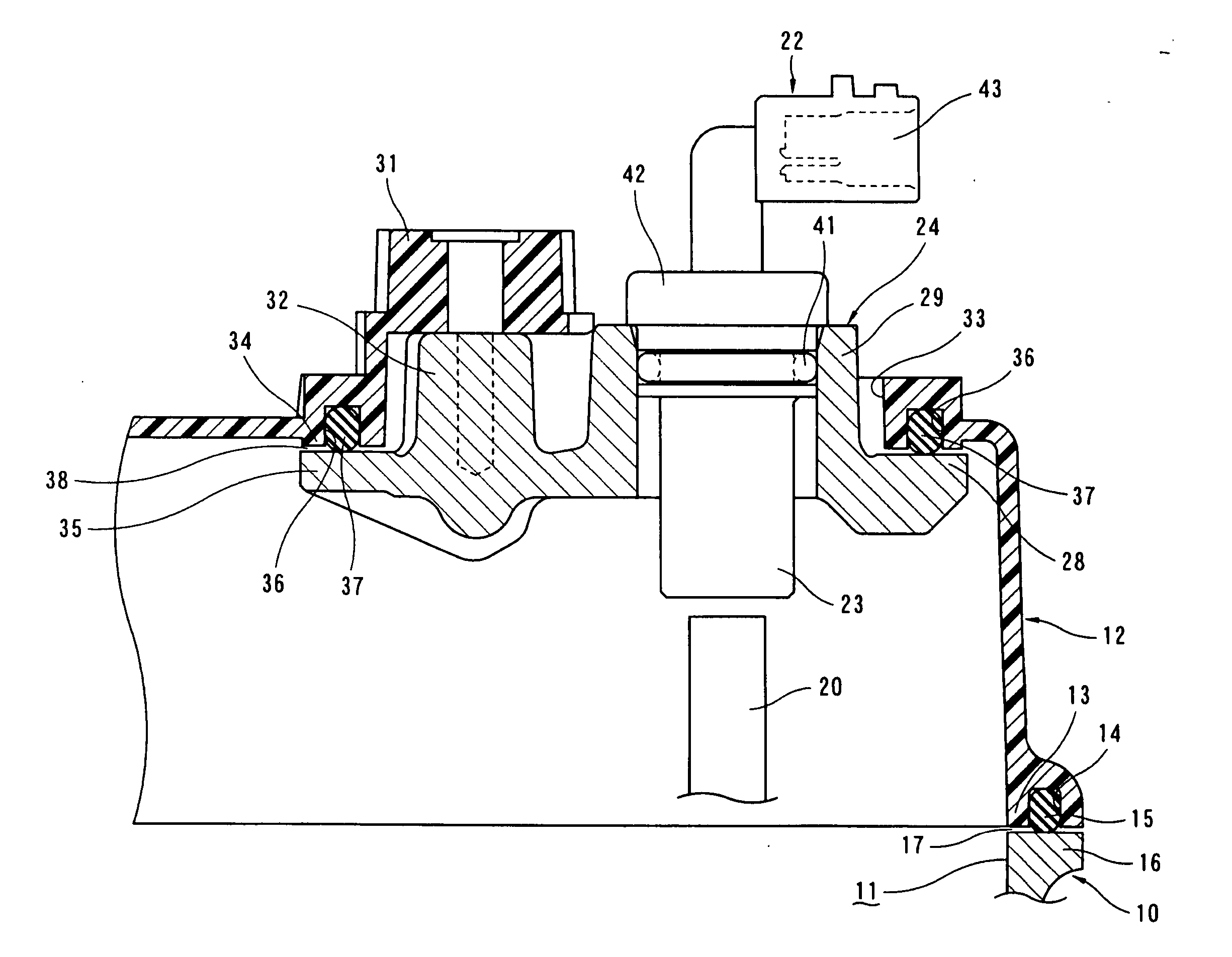
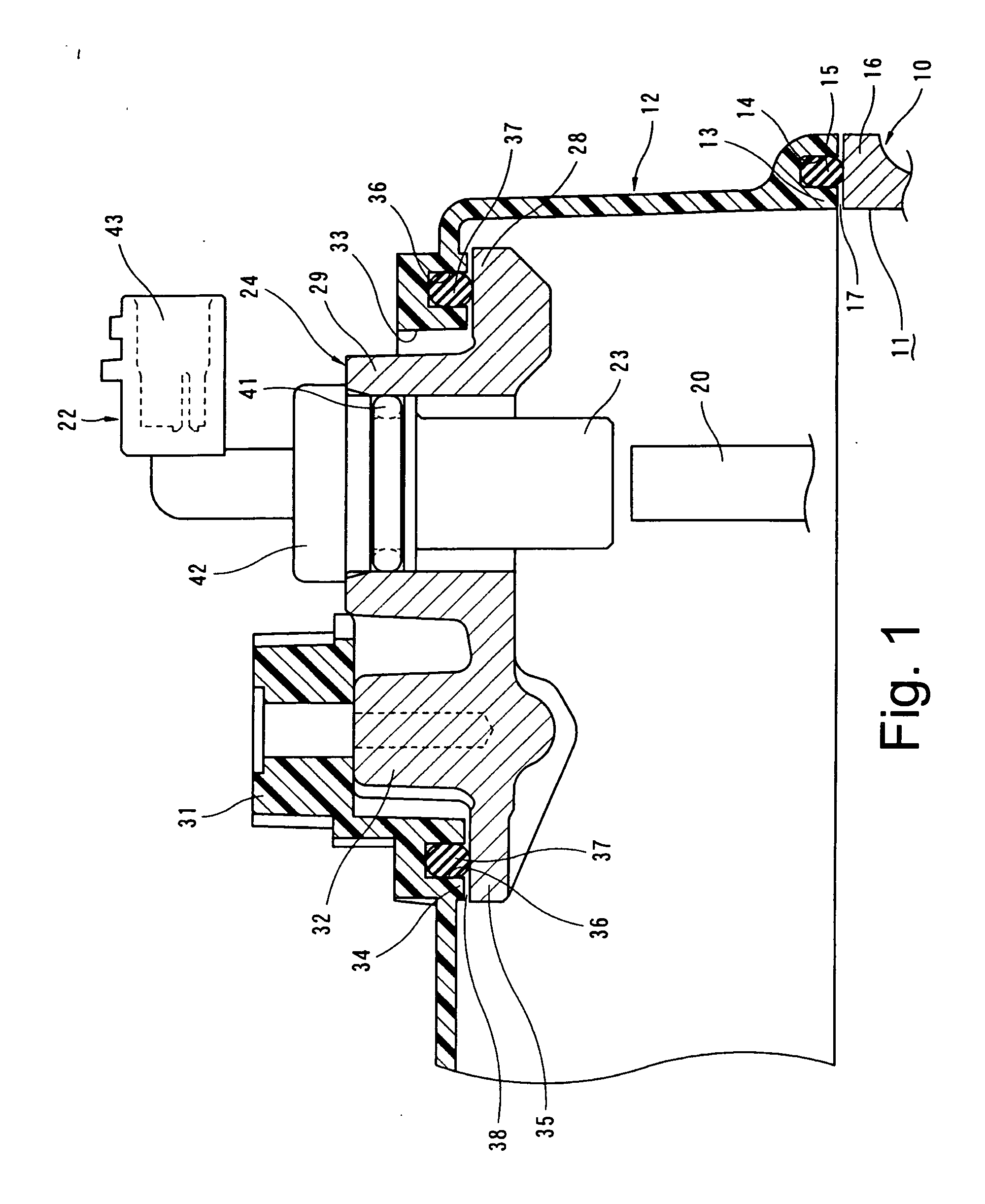
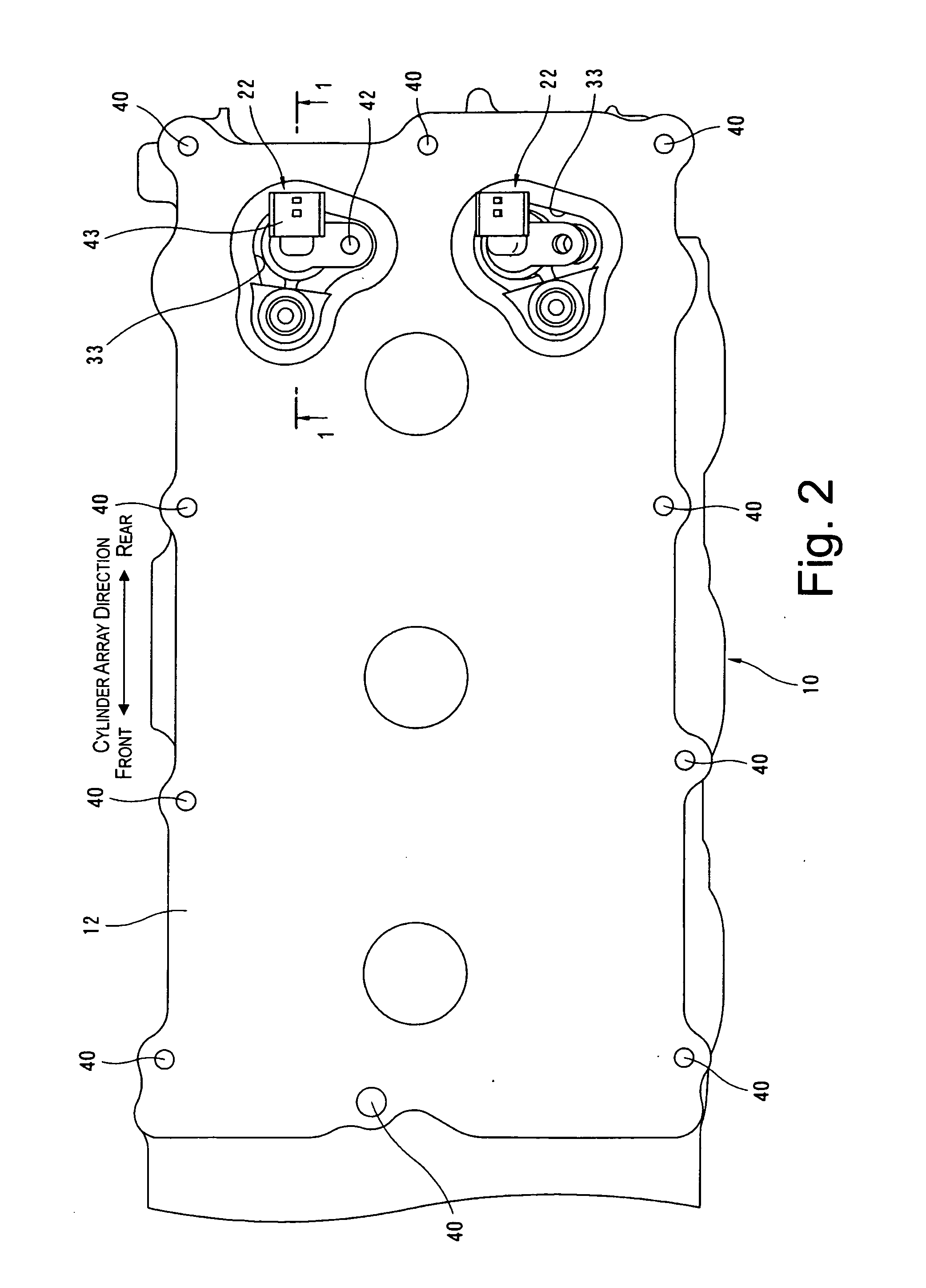
[0023] FIGS. 1 to 8 show an internal combustion engine with a cam angle sensor mounting structure in accordance with one embodiment of the present invention. The internal combustion engine is, for example, a V-type 6-cylinder engine as shown in FIG. 8 with the intake system (INT side) on the inner side of banks, and the exhaust system (EXH side) on the outer side of the banks. The internal combustion engine is preferably transversely installed in an engine room at the front of a vehicle. As used herein, the terms “up” and “down” are used with respect to up-down direction of cylinders (i.e., up-down d...


PUM


Abstract

A cam angle mounting structure includes a cylinder head, a sensor bracket and a head cover. The cylinder head is configured and arranged to rotatably support a camshaft. The sensor bracket is configured and arranged to support a cam angle sensor. The sensor bracket is mounted on the cylinder head with the sensor bracket contacting the cylinder head. The head cover is non-rigidly mounted on the cylinder head and the sensor bracket via at least one gasket to cover a top opening of the cylinder head with a space being formed around the at least one gasket between the head cover and the cylinder head and between the head cover and the sensor bracket.

Description

CROSS-REFERENCE TO RELATED APPLICATIONS [0001] This application claims priority under 35 U.S.C. § 119 to Japanese Patent Application No. 2005-213576. The entire disclosure of Japanese Patent Application No. 2005-213576 is hereby incorporated herein by reference. BACKGROUND OF THE INVENTION [0002] 1. Field of the Invention [0003] The present invention relates to a mounting structure of a cam angle sensor configured and arranged to detect rotation angle of a camshaft of an internal combustion engine. [0004] 2. Background Information [0005] An internal combustion engine is usually provided with cam angle sensors to detect rotation angles (positions) of camshafts of intake and exhaust valves. The cam angle sensor is disposed in a radial outer direction of a signal plate, which serves as a detection part, provided at a rear end of the camshaft and configured and arranged to detect projections and grooves formed in the signal plate. Japanese Patent No. 3,431,505 discloses a cam angle moun...

Claims


Application Information

Patent Timeline
Patent Type & Authority Applications(United States)
IPC IPC(8): G01M19/00F01M9/10G01M99/00
CPCF01L1/053F01L1/34F01L2820/041F01L2001/0537F01L2001/34436F01L1/46F02D35/00F02F1/24F02F7/00
Inventor TOOYAMA, HIDEAKINOMURA, SHINNETSU, HIRONAO
Owner NISSAN MOTOR CO LTD
Why Eureka
Try Eureka