
Method for driving a flat panel display

Active Publication Date: 2007-01-25
AU OPTRONICS CORP
View PDF5 Cites 3 Cited by
  • Summary
  • Abstract
  • Description
  • Claims
  • Application Information

AI Technical Summary

Benefits of technology

[0011] Therefore, an object of the invention is to provide a method for driving a flat panel display for efficiently reducing power consumption of large-sized flat panel displays.
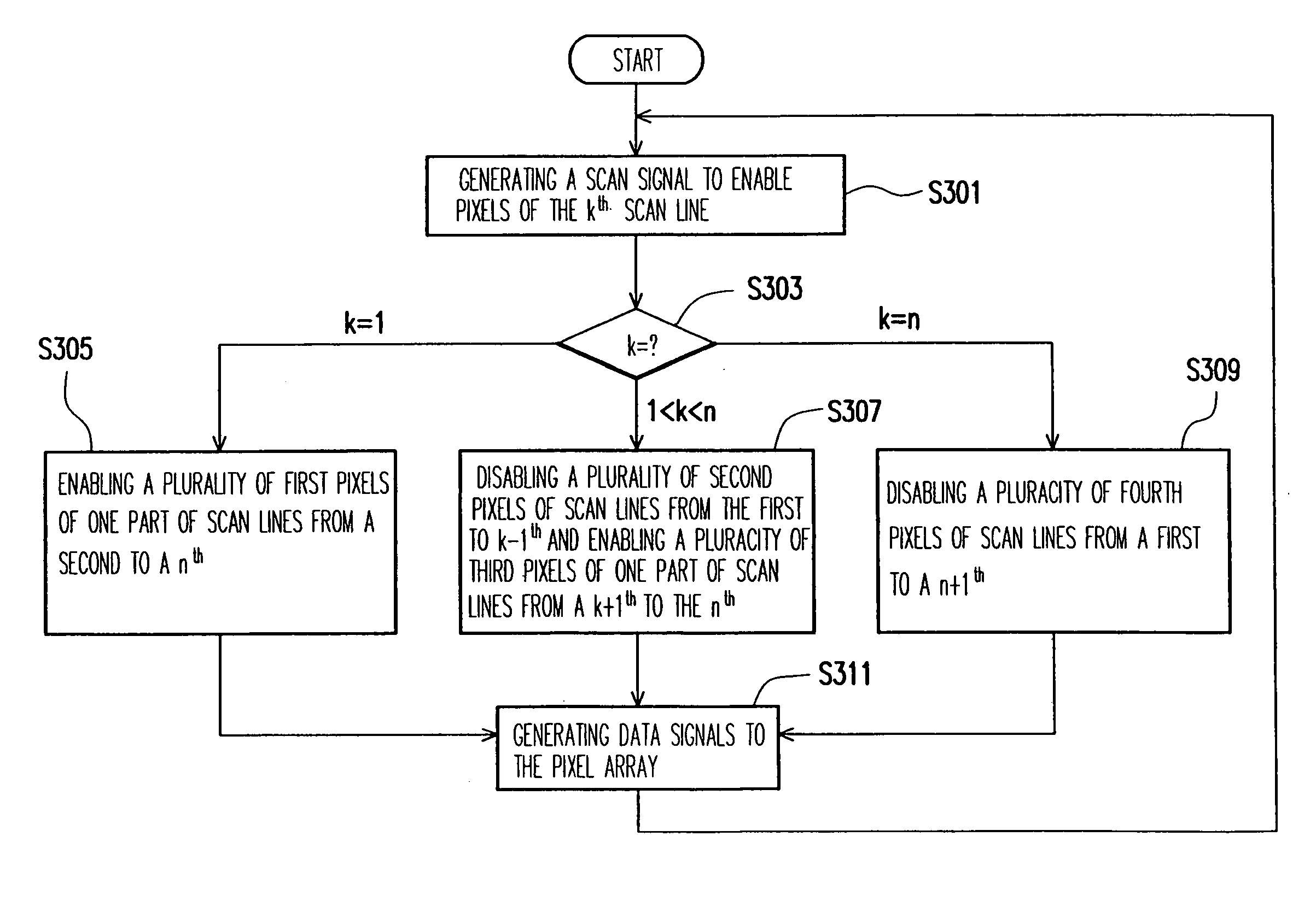
[0014] As above-mentioned, when pixels of the kth scan line are enabled, some pixels of a part of the rest scan lines are also enabled. Therefore, as driving pixels coupled to the kth scan line, data signals will also pre-charge the other enabled pixels at the same time. As a result, it consumes less current when driving the pre-charged pixels of the rest scan lines.

Problems solved by technology

Despite of advantages it may have, a conventional cathode-ray tube (CRT) display not only is large in bulk that occupies too much room because of its intrinsic structure of the electronic cavity, but also radiates rays which may hurt human eyes.
Consequently, refreshing frequencies of scan lines are demanded to be more and more rapid, which contradicts the designs for power saving by system engineers.
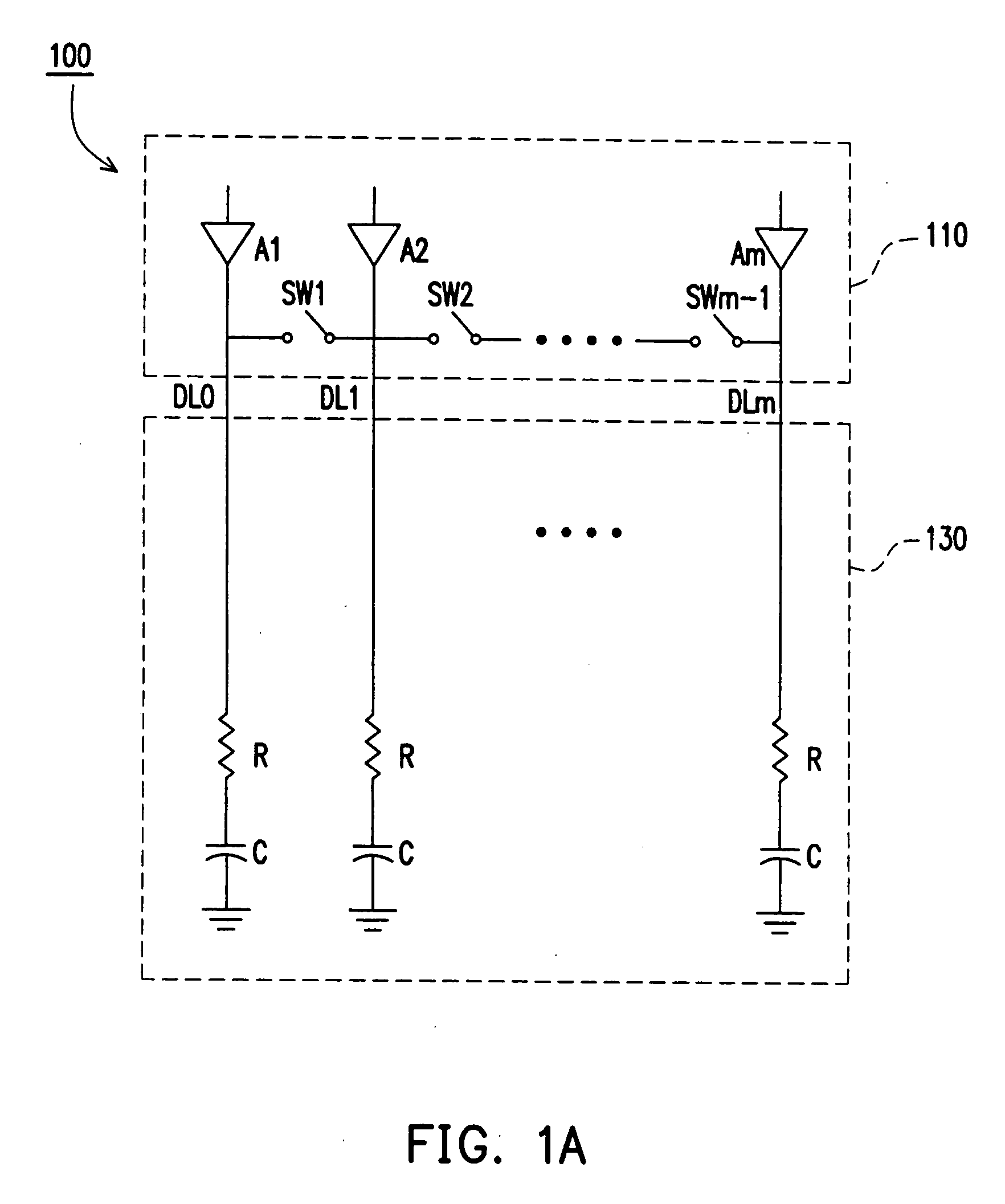
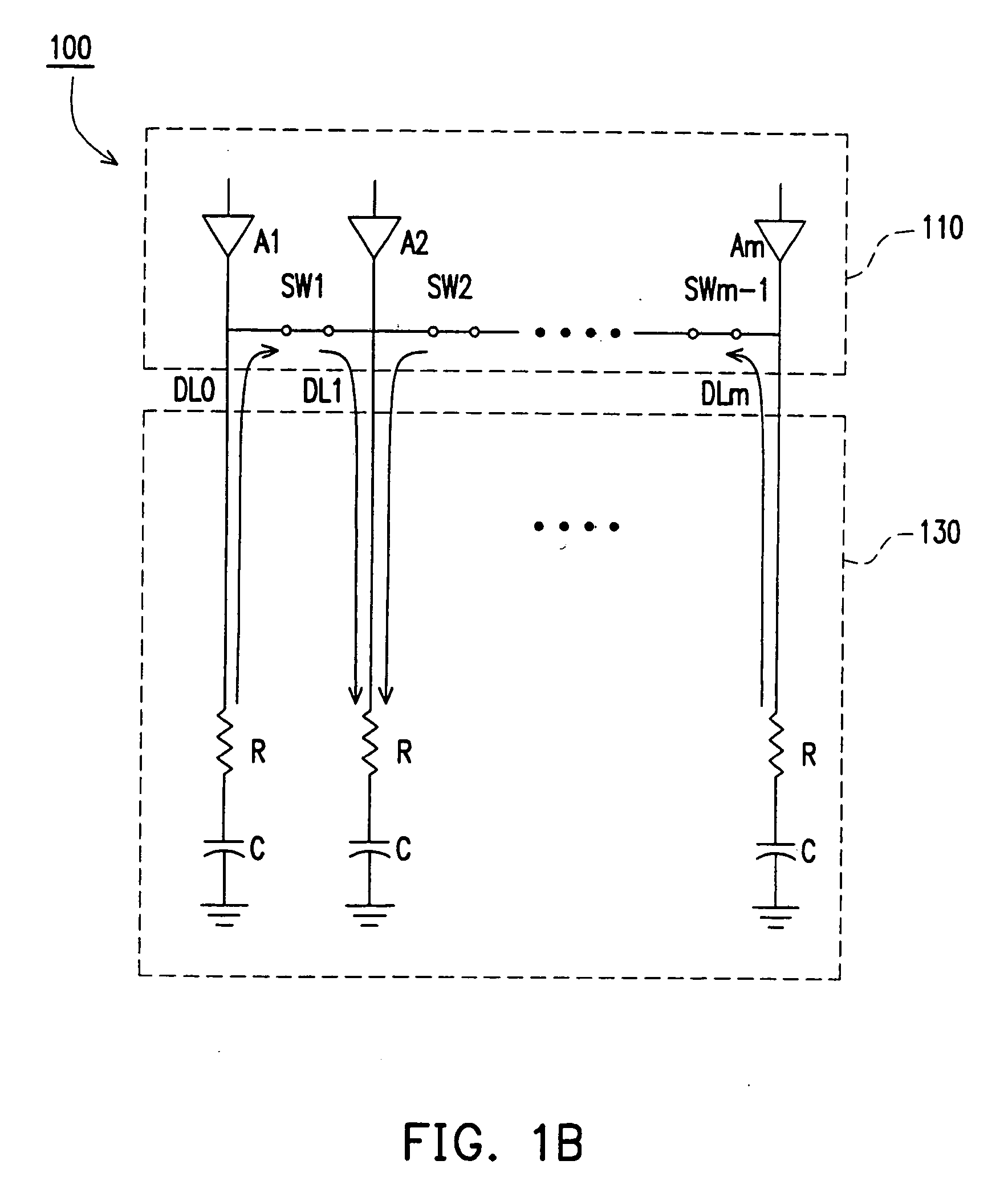
Unfortunately, whenever an overall slew rate of the source driver 110 slows down, an efficiency of the source driver 110 will drop down accordingly.
Therefore, such a source driver can not satisfy the requirements of the new generation flat panel displays which demand higher resolution, higher load and larger size.

Method used


Image

  • Method for driving a flat panel display
  • Method for driving a flat panel display
  • Method for driving a flat panel display

Examples


Embodiment Construction

[0021]FIG. 2 is a block diagram for a circuit of a flat panel display 200 according to an embodiment of the invention. Referring to FIG. 2, the flat panel display 200 includes a pixel array 210. The pixel array 210 is coupled to a gate driver 223 via a, plurality of scan lines SL0 through SLn and coupled to a source driver 221 via a plurality of data lines DL0 through DLm, wherein n and m are positive integers greater than 1. The flat panel display 200 further includes a timing sequence control circuit 225 which controls the source driver 221 and the gate driver 223.

[0022] In the pixel array 210, the data lines DL0 through DLm are parallel with each other taking along a first orientation, and the scan lines SL1 through SLn are parallel with each other taking along a second orientation. The first orientation and the second orientation can be perpendicular with each other. The data lines DL0 through DLm and the scan lines SL1 through SLn are alternately distributed without being in t...


PUM

PropertyMeasurementUnit
Fractionaaaaaaaaaa
Polarityaaaaaaaaaa

Abstract

A method for driving a flat panel display is provided. The flat panel display has n scan lines, wherein n is a positive integer. Each of the scan lines is coupled to a plurality of pixels. The driving method according to the invention includes the steps as follows: when pixels coupled to a kth scan line are enabled, pixels coupled to the scan lines from the first to k−1th are disabled and pixels coupled to at least a part of scan lines from k+1th to nth are enabled, thus pre-charging the enabled pixels of scan lines from k+1th to nth is performed thereby, wherein k is a positive integer.

Description

CROSS-REFERENCE TO RELATED APPLICATION [0001] This application claims the priority benefit of Taiwan application serial no. 94124262, filed on Jul. 19, 2005. All disclosure of the Taiwan application is incorporated herein by reference. BACKGROUND OF THE INVENTION [0002] 1. Field of the Invention [0003] The present invention relates to method for driving a flat panel displays, and particularly to a method for driving a flat panel display for reducing power consumption of a source driver by modified scan signals, and therefore for reducing the system power consumption. [0004] 2. Description of Related Art [0005] In order to catch up with the modern lifestyle, video and image devices are becoming slimmer and lighter. Despite of advantages it may have, a conventional cathode-ray tube (CRT) display not only is large in bulk that occupies too much room because of its intrinsic structure of the electronic cavity, but also radiates rays which may hurt human eyes. Therefore, accompanying the...

Claims


Application Information

Patent Timeline
IPC IPC(8): G09G3/36
CPCG09G3/3614G09G2330/023G09G2310/0251G09G3/3648
Inventor YI, CHIEN-YU
Owner AU OPTRONICS CORP
Learn More