Light source driving device

a driving device and light source technology, applied in the direction of light sources, lighting apparatus, instruments, etc., can solve the problems of large noise generation, substantial increase in etc., and achieve the effect of reducing noise generated during driving, increasing manufacturing time or manufacturing cos

Inactive Publication Date: 2007-01-25
TOSHIBA MATSUSHITA DISPLAY TECH
View PDF1 Cites 8 Cited by
  • Summary
  • Abstract
  • Description
  • Claims
  • Application Information

AI Technical Summary

Benefits of technology

[0008] The present invention has been developed in view of such problem, and an object is to provide a light source driving device ...

Problems solved by technology

Since the cold-cathode fluorescent tube repeatedly turns on and off in accordance with this alternating current, the luminance can be adjusted over a broad range, but a very large noi...

Method used


Image

  • Light source driving device
  • Light source driving device
  • Light source driving device

Examples


Embodiment Construction

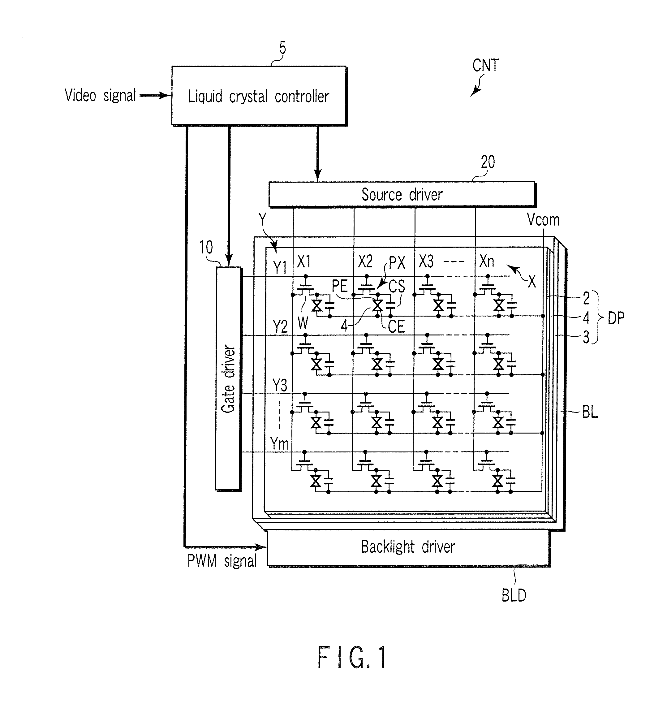
[0017] There will be described hereinafter a liquid crystal display device according to one embodiment of the present invention with reference to the accompanying drawings. FIG. 1 schematically shows the configuration of this liquid crystal display device. The liquid crystal display device includes a transmissive type liquid crystal display panel DP having a plurality of liquid crystal pixels PX; a backlight BL which illuminates the liquid crystal display panel DP, and a control unit CNT which controls the liquid crystal display panel DP and the backlight BL. The liquid crystal display panel DP has a structure in which a liquid crystal layer 4 is held between an array substrate 2 and a counter substrate 3.

[0018] The array substrate 2 has a plurality of pixel electrodes PE arrayed in a matrix on a transparent insulating substrate such as glass, a plurality of gate lines Y (Y1 to Ym) arranged along the rows of pixel electrodes PE, a plurality of source lines X (X1 to Xn) arranged alo...


PUM


Abstract

A light source driving device includes a switching circuit which switches a direct-current voltage supplied externally, a piezoelectric transformer which raises the voltage output from the switching circuit and which allows an alternating current to flow through a cold-cathode fluorescent tube, and a control circuit to change the duty ratio as a ratio per unit time at which the alternating current is output from the switching circuit in order to dim the cold-cathode fluorescent tube. The switching circuit includes resistors RA, RB which set the tilt of the envelope waveform to increase the fall time of the envelope waveform of the alternating current flowing through the cold-cathode fluorescent tube.

Description

CROSS-REFERENCE TO RELATED APPLICATIONS [0001] This application is based upon and claims the benefit of priority from prior Japanese Patent Application No. 2005-214460, filed Jul. 25, 2005, the entire contents of which are incorporated herein by reference. BACKGROUND OF THE INVENTION [0002] 1. Field of the Invention [0003] The present invention generally relates to a light source driving device for a liquid crystal display panel, particularly to a light source driving device which drives a discharge lamp light source such as a cold-cathode fluorescent tube. [0004] 2. Description of the Related Art [0005] Liquid crystal display panels are broadly utilized as displays for personal computers, portable information terminals, television receivers, car navigation systems and the like. In a case where the liquid crystal display panel is of a transmissive type, in general, a discharge lamp light source such as a cold-cathode fluorescent tube is disposed as a backlight in the liquid crystal ...

Claims


Application Information

Patent Timeline
IPC IPC(8): G09G3/36
CPCG09G3/3406H05B41/2822G09G3/3611
Inventor OOYAMA, ATSUNORI
Owner TOSHIBA MATSUSHITA DISPLAY TECH
Why Eureka
Try Eureka