Data processing method and system

Inactive Publication Date: 2007-01-25
IBM CORP
1 Cites 63 Cited by

AI-Extracted Technical Summary

Problems solved by technology

This method can only be applied, without additional aids, to flow graphs that are well-structured enough.
If a flow graph is irreducible, auxiliary methods such a...

Benefits of technology

[0019] Preferably, the transformation rules further include a third rule (Cst) for the elimination of an edge that links a node to another node, if and only if the source node has only one outgoing edge and the target node has only one incoming edge, a fourth rule (Cs) for the elimination of an edge that links a node to another node, if and only if the source node has only one outgoing edge, and a fifth rule (Ct) for the elimination of an edg...

Abstract

A data processing method including receiving a model of a directed graph, the model defining one or more nodes and edges of the directed graph, each node having a corresponding behavior defining the execution of the node, and each edge having corresponding data defining a directional link from one node to another node and having a corresponding condition defining when the edge is to be traversed; executing, according to a predefined priority, a series of transformation rules, the transformation rules comprising a first rule for the elimination of an edge that links a node to itself, and a second rule for the elimination of an edge that links a node to another node, each rule including an update operation defining a new behavior for the or each node affected by the elimination of the edge; and creating an output according to the performance of the transformation rules.

Application Domain

Technology Topic

Image

  • Data processing method and system
  • Data processing method and system
  • Data processing method and system

Examples

  • Experimental program(1)

Example

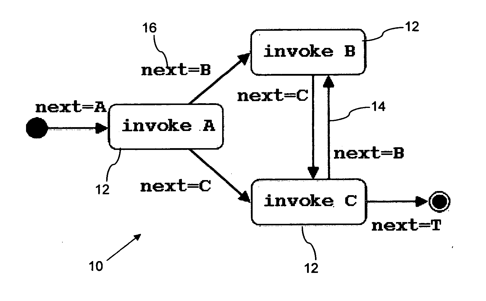
[0029]FIG. 1 shows a simple directed graph 10, comprised of nodes 12 and edges 14. The graph 10 in FIG. 1 is shown graphically, but can equally be represented in a large number of different ways, such as a list of nodes 12 and edges 14, or, in the case of specific programming and modelling languages, as a series of terms as defined by those languages. Any such representation can be considered to be a model of a directed graph.
[0030] In order to represent business processes and workflows, the standard definition of a flow graph is extended. Firstly, a node 12 is assumed to be annotated with a behavior which defines the execution of the node 12. The behavior will be described with a behavioral metamodel, but a simple string representation will be used for compactness of the representation. The behavior of node A in FIG. 1 is written as invoke A.
[0031] Secondly, to every edge 14 a condition 16 called a guard is assigned such that the guards of all edges leaving a node are mutually exclusive and exhaustive. The guards 16 state which edge 14 will be fired by the node 12 when the execution of the node 12 terminates. The condition 16 defines when an edge 14 is to be traversed.
[0032] The guards 16 in a flow graph are originally expressions over variables within the scope of a node 12 that tests whether the guards 16 are true. Because the setting of these variables and the tests may become separated during any transformation, additional variables are introduced and maintained in order to keep the intended execution logic correct.
[0033] In an initial transformation step a single variable, called “next” is introduced, in the scope of all nodes in the flow graph, i.e., readable and writable by all nodes. It is used to store the next node to be executed. Secondly, the initial behavior invoke N for a node N is replaced by invoke N; if (c1) { next := N1 } ... if (cn) { next := Nn }
where ci is the original guard of the edge N->Ni (for i=1 to n). Lastly, the initial guard ci for every edge N->Ni is replaced with next=Ni. The simple schema in the initial transformation step uses the variable next to store the goto-target. More elaborate schemes are possible.
[0034] The processing of any model of a directed graph comprises the executing, according to a predefined priority, of a series of transformation rules. The two transformation rules are based on a pattern that comprises an edge M->N with its source node M and its target node N. A first rule is for the elimination of an edge that links a node to itself and is called L, and the second rule for the elimination of an edge that links a node to another node and is called C. The second rule C merges two nodes and simultaneously removes one or more than one edge. Because a flow graph contains only a finite number of nodes and edges and each rule removes at least one edge, the execution of the rules eventually terminates. The result is a flow graph with a single node and no edges, because otherwise one of the rules could still be applied.
[0035] The application of a rule in a transformation step modifies the flow graph by merging nodes and removing edges, updates the behavior of nodes, and may change the guard of edges. The result of the transformation is the behavior of the single remaining node when the rules can no longer be applied.
[0036]FIG. 2 depicts the transformation rule L, which is applicable to an edge M->N if M=N. The self-loop with guard c1 is removed and the node with behavior bodyN has its behavior modified during the transformation step. The behavior of node N is wrapped into a repeat-loop with the guard of the removed edge as its loop-condition. All other edges of node N remain unchanged. This rule is responsible for introducing loops into the behaviors of the nodes.
[0037]FIG. 3 depicts the transformation rule C, which is applicable to an edge M->N if M not=N. The nodes M and N with respective behaviors bodyM and bodyN are merged during the transformation step, the edge leading from M to N is removed, and the other edges with their guards are adapted appropriately. The behavior of the resulting node executes bodyM only if c2|c3 (the disjunction of all guards of incoming edges of M) is true while bodyN is executed only if c1|c4|c5 (the disjunction of all guards of incoming edges of N) is true. The symbol | used in the text and figures, represents the logical or.
[0038] The new node, produced in FIG. 3, inherits all incoming and outgoing edges of M and N except for the removed edge. The guards of incoming and outgoing edges remain unchanged except if both nodes originally had an edge from or to a third node (here nodes X and Y), the two edges are merged and their guards are combined with a disjunction. This rule is responsible for introducing conditionals into the behavior of the nodes.
[0039] Rule C wraps the original behavior of both nodes into if-statements. This is not always necessary, because if the source node has only one outgoing edge or the target node has only one incoming edge, then this edge is the edge that will be removed by the transformation step.
[0040] A more flexible strategy for processing the model of the directed graph can be achieved using further additional rules (the order in which rules are applied to a model is discussed in detail below). Three further rules are discussed, each of which is a specialization of rule C.
[0041] A third rule Cst is shown in operation in FIG. 4. This rule is applicable when the two nodes M and N build a simple sequence. No if-statement is therefore necessary. The third rule is for the elimination of an edge that links a node to another node, if and only if the source node has only one outgoing edge and the target node has only one incoming edge.
[0042] A fourth rule Cs, shown in FIG. 5, is applicable if node M has only one outgoing edge, the edge M->N. The guard of this edge is always true, and the second if-statement is not necessary, because bodyN is executed when the merged node is reached. The fourth rule Cs is for the elimination of an edge that links a node to another node, if and only if the source node has only one outgoing edge.
[0043] A fifth rule rule Ct, shown in FIG. 6, is applicable if node N has only one incoming edge, the edge M->N. Node N is only reachable through node M and the first if-statement is therefore not necessary. The fifth rule Ct is for the elimination of an edge that links a node to another node, if and only if the target node has only one incoming edge.
[0044] The conditions in guards and if-statements can often be simplified. When a node has only one outgoing edge, the guard is true and can be eliminated. Further, the transformation rules may lead to disjunctions such as next=N|next=N that contain the same term more than once and can be simplified. In the discussion below, to keep behaviors compact, terms such as next=A|B will be used instead of next=A|next=B.
[0045] The behavior of the flow graph is not changed through the introduction of the variable next in the initial transformation step. Likewise, the data processing method will produce an output that is functionally equivalent to the original flow graph. This can be shown by demonstrating that the rules L and C preserve the behavior of the original nodes as they are executed.
[0046] For all transformation rules the guards of all outgoing edges of a new node are still mutually exclusive and exhaustive. They may no longer form a tautology because one edge is removed by L, but its guard can never be true after the repeat-loop.
[0047] The transformation rules L and C (and the variations of C) do not change the execution logic of any transformed node(s). The proof for rule L is straightforward because the guards of the outgoing edges, i.e., the conditions c1 and c3 in FIG. 2, stay correct for the old and the new behavior and these guards are mutually exclusive. The proof for C shows that the behavior of the new node is correct, that the guards of the incoming edges cannot trigger unintended behavior inside the new node, and that the behavior of the new node cannot enable the guards of the wrong outgoing edges, i.e., the conditions c6 to c9 in FIG. 3. The first two points are obvious and the last point is guaranteed because the guard of an edge A->B can only contain a disjunction of terms next=ci where each ci is either B or has been merged in a previous step into B. A node is never merged into more than one node.
[0048] An example of the effect of the data processing method is now described with respect to FIG. 7, which shows one possible implementation where the input is a graphical model, the output a textual model, and the result is produced by an update transformation. This has been selected because one important application of the transformation is the removal of cycles in the graphical representation of business process models in order to compile them into the Business Process Execution Language for Web Services, called BPEL4WS or simply BPEL.
[0049]FIG. 7 shows the transformation, with the rules L, Cs and Ct applied to the flow graph of FIG. 1 after the initial transformation step to set and use the newly introduced variable next. In a first step, application of rule Cs merges node B with C and leads to the flow graph with a self-loop in FIG. 7a. The self-loop is eliminated next using rule L as shown in FIG. 7b where the repeat-loop replaces the self-loop. In the last step resulting in FIG. 7c, rule Ct is applied to demonstrate how the guard of the edges are used. Cst could have been applied instead to avoid the unnecessary if-statement with condition next=B|C.
[0050] To complete the transformation, the initial node can be removed and becomes the initialization, and the final node disappears completely into implicit termination. If there would have been more than one edge leaving the initial node, the initialization would have become a set of if-statements that initialize the variable next. If the final node is resolved last, only a single edge remains in the flow graph and rule Cst can be applied. It is clear that the empty behavior of the final node has no influence on the program. Terms next=T never appear in conditions of if-statements or repeat-loops.
[0051] The complete program for the flow graph in FIG. 1 is (with conditions that are always true removed): next := A invoke A if (AB) {next := B} if (AC) {next := C} repeat { if (next = B) { invoke B next := C } invoke C if (CB) {next := B} if (CT) {next := T} } while (next = B)
[0052] The algorithm that performs the execution of the transformation rules can be summarised as follows: Graph graph := input Set edges := graph.edges List strategy := [Rule1, Rule2, ..., Rulen] boolean done := false do while(not done) { boolean applied := false for each rule in strategy { for each edge in edges { if (edge matches rule.pattern) { apply rule.updateOperation(edge) applied := true } } until (applied) } until (applied) if (edges empty or not applied) done := true } Set nodes := graph.nodes if (nodes contains only one element node) { output := node.behavior } else { output := undefined }
[0053] In this pseudo-code the keywords and literals such as boolean are shown in bold to distinguish them from variables such as done, and: = is used for assignments. The “for each” construct takes the next element from a List, e.g., strategy, or selects an arbitrary element from a Set, e.g., edges. The match keyword tests whether the pattern of a rule, i.e., the left side, matches, e.g., tests whether the source and target of an edge are the same node for rule L. The apply keyword applies the update operation of a rule, i.e., the right side, to the matching edge. The algorithm loops through all the rules and for one rule through all the edges until it finds a matching edge. In this case, it applies the update operation and starts again with the first rule. If the set of edges is empty, or if none of the rules can be applied to an edge anymore, the algorithm terminates.
[0054] If the graph at the end contains only one single node, the behavior of this node is the result. This is always the case if the strategy contains rule C and rule L. Strategies with only some of the rules, however, may terminate when the graph still contains edges and more than one node. In this case, the result of the transformation is undefined.
[0055] As already seen in FIG. 7, transformations based on some or all five rules are not confluent. Though the resulting programs are not equal, they are functionally equivalent. Consequently, different strategies can be used to run the transformation in order to shape the resulting program. In other words, the transformations defined by the five rules build a family of transformations, and the strategy determines the family member.
[0056] Because each step of the transformation removes at least one edge, and because models are finite and therefore may only contain a finite number of edges, the algorithm will always terminate eventually. Independent of the priorities given to the rules, the result will always be functionally equivalent to the original model.
[0057] However, the strategy, i.e., the priorities of the rules, will influence the result. If rule C has highest priority, it will be applicable as long as there are at least two nodes left in the model, because initially any node is reachable from the start node, the termination node is reachable from any node, and the update operations do not affect this. In other words, rule C will merge nodes until only a single node is left. If this node has an outgoing edge leading to itself, i.e., a self-loop, the original model was cyclic, and a single application of rule L will remove this last remaining edge. Thus, the number of repeat-loops is minimized. If rule L has highest priority, self-loops are removed as soon as possible. Thus, the number of repeat-loop is maximized.
[0058] This data processing method functions independently of the rule selection strategy, i.e., the priorities assigned to the rules), because different requirements lead to different strategies. The strategy can be considered as a list of rules ordered by priority (higher priority before lower priority). The list [rule L, rule C] is an example of a strategy and corresponds to the case discussed above where the number of repeat-loops is maximized. However, a strategy where rule Cst has a lower priority than rule C, rule Cs or rule Ct, will never apply rule Cst.
[0059] There are two decisions made when selecting the strategy, the subset of rules to be used, and the priorities of those rules. The first decision determines the set of flow graphs that can be transformed completely to a structured program. The second decision influences the quality of the transformation result. In general, if L has the highest priority, the resulting program contains more repeat-loops, and these loops contain only code that is part of the cycle. Therefore, the number of if-statements is minimal. If, on the other hand, L has lowest priority, the resulting program contains a lower number of repeat-loops, but unnecessary code is moved into these loops protected by if-statements to ensure that the code is only executed when necessary.
[0060] If L has the lowest priority then, if the rule-set contains Ct, this strategy has the tendency to move nodes to the right of a cycle into the loop. Similarly, if the rule-set contains Cs, nodes to the left of the cycle may get moved into the loop. Because C generalizes these two rules, nodes on both sides of the cycle are consumed before the loop is resolved. In general, rule C without the help of any other rule can transform any flow graph into a flow graph with a single node. If this node has a self-loop, the flow graph was cyclic and a single application of rule L at the end of the transformation can remove the self-loop. Otherwise, the flow graph was acyclic.
[0061] Rule-sets containing Cs and Ct not only merge nested but also overlapping cycles. Overlapping cycles result in a single loop in case the rule-set contains L, Cs, and Ct, and the strategy gives L lowest priority. Disjoint cycles, on the other hand, can only be resolved into a single loop if the rule-set contains C. A strategy to keep disjoint loops separate may thus use all rules but give Cs and Ct high, L medium and C low priority.
[0062] In addition to determining the order for which rules should be executed, the order in which the nodes of the model should be processed is also to be determined. Generally, the initial and final nodes may preferably be resolved as late as possible, because they become the initialization and implicit termination of the resulting program. Otherwise, the nodes are rather indistinguishable from the transformation's point of view, as long as only local properties of the flow graph are considered. The only distinguishing features are the number of incoming and outgoing edges of the source and target node, whether source and target node are the same, and whether source and/or target node have a self-loop.
[0063] The preconditions of the five transformation rules describe local patterns in flow graphs. To determine whether L is applicable, a pattern with a single node and a self-loop is matched. To determine whether one of the other four rules is applicable, a pattern with two distinct nodes connected through an edge and, with possibly some additional rule-specific constraints is matched.
[0064] The strategy can be further refined through additional and more complex patterns than the preconditions of the rules in the rule-set. For example, the following strategy is possible. The rule-set contains L and Ct, and Ct has the higher priority. Instead of applying L blindly, when Ct was no longer applicable, we used a pattern that preferred nodes with a self-loop and only one other incoming edge over other nodes with a self-loop. This strategy minimized the number of repeat-loops, because the node and its predecessor became applicable for Ct after removal of the self-loop.
[0065] The fact that the three rules Cs, Ct, and C have the tendency to move nodes unnecessarily into loops if rule L has lowest priority, may not always be desired. To improve this situation in particular, and to fine-tune the strategy in general, patterns involving more than an edge with its source and target node or even global properties of the flow graph may be used, though in general it is better to stay with local properties as long as possible for performance reasons.
[0066] The data processing method effectively uses a family of algorithms that allow the transformation of sequential behavioral models with unstructured continuations, for example gotos, into behavioral models with only the structured constructs for loops, for example, repeat-loops, and conditionals, such as if-statements. The algorithms can be applied to any subject that lends itself to graph reduction, such as textual models, like programming languages, in order to eliminate gotos or to graphical models, for example, business processes or workflows, in order to remove unstructured cycles. The family of algorithms is based on the two general transformation rules, L and C, and three specializations of C, called Cs, Ct, and Cst. The rule L is responsible for the introduction of structured loops by resolving gotos that go “upstream”, and the rule C is responsible for the introduction of conditionals by resolving gotos that go “downstream”.
[0067] A transformation algorithm, i.e., a member of this family, can be defined by selecting a subset of rules and by choosing a rule-application strategy. Depending on the rule-set selected, any source model or only some source models can be completely transformed. This has the advantage that no auxiliary methods such as node-splitting are needed in order to transform the desired set of source models.
[0068]FIG. 8 shows an example of a data processing system 18 (shown schematically) that can be used to execute the data processing method. The system comprises a processor 20, a display device 22 and user input devices 24. The processor 20 is arranged to receive a model 26 of a directed graph 10.
[0069] The model 26 defines a series of nodes 12 and edges 14 of the directed graph 10, each node 12 having a corresponding behavior 28 defining the execution of the node 12, and each edge 14 having corresponding data 30 defining a directional link from one node 12 to another node 12 and having a corresponding condition 16 defining when the edge 14 is to be traversed.
[0070] As discussed above, the processor 10 executes, according to a predefined priority 32, a series of transformation rules C, L, Cst, Cs and Ct, each rule including an update operation defining a new behavior 28 for each node affected by the elimination of the edge 14, and creates an output 34 according to the performance of the transformation rules.

PUM

no PUM

Description & Claims & Application Information

We can also present the details of the Description, Claims and Application information to help users get a comprehensive understanding of the technical details of the patent, such as background art, summary of invention, brief description of drawings, description of embodiments, and other original content. On the other hand, users can also determine the specific scope of protection of the technology through the list of claims; as well as understand the changes in the life cycle of the technology with the presentation of the patent timeline. Login to view more.

Similar technology patents

Classification and recommendation of technical efficacy words

People also interested in

Why Eureka
Try Eureka