Optical module for a motor vehicle lighting device

a technology for optical modules and motor vehicles, applied in the direction of refractors, light and heating apparatus, transportation and packaging, etc., can solve the problems of low luminous efficiency, low efficiency, and insufficient ratio between the light emitted by the lamp and the light reconstructed at the output of the optical module, so as to achieve compact optical modules and improve efficiency. , the effect of small siz

Inactive Publication Date: 2007-01-25
VALEO VISION SA
View PDF3 Cites 26 Cited by
  • Summary
  • Abstract
  • Description
  • Claims
  • Application Information

AI Technical Summary

Benefits of technology

[0021] the aim can be similar optical performance with less powerful light sources and / or less complex reflectors;
[0039] The shield can be a movable shield making it possible to produce a dual-function or multi-function headlight, in particular a low-beam / high-beam dual-function module or a multi-function module.

Problems solved by technology

Whether the shield is fixed or movable, and irrespective of the type of cut-off it defines in the beam, it remains that all the luminous flux that is intercepted by the shield is lost, and the luminous efficiency, that is to say the ratio between the light emitted by the lamp and that reconstructed at the output of the optical module, is therefore not very satisfactory.

Method used


Image

  • Optical module for a motor vehicle lighting device
  • Optical module for a motor vehicle lighting device
  • Optical module for a motor vehicle lighting device

Examples


Embodiment Construction

[0048] The elements appearing in different figures keep the same references.

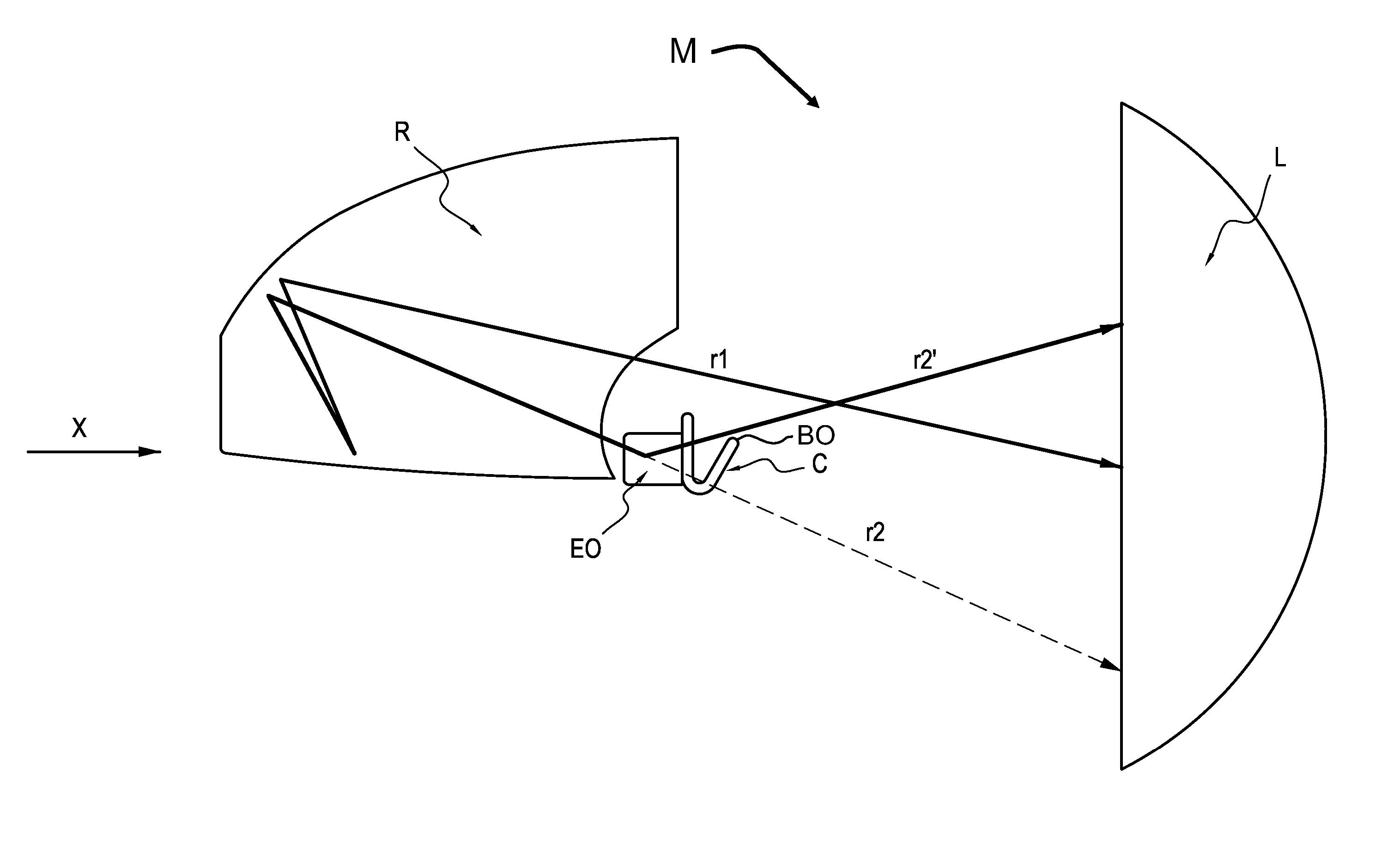
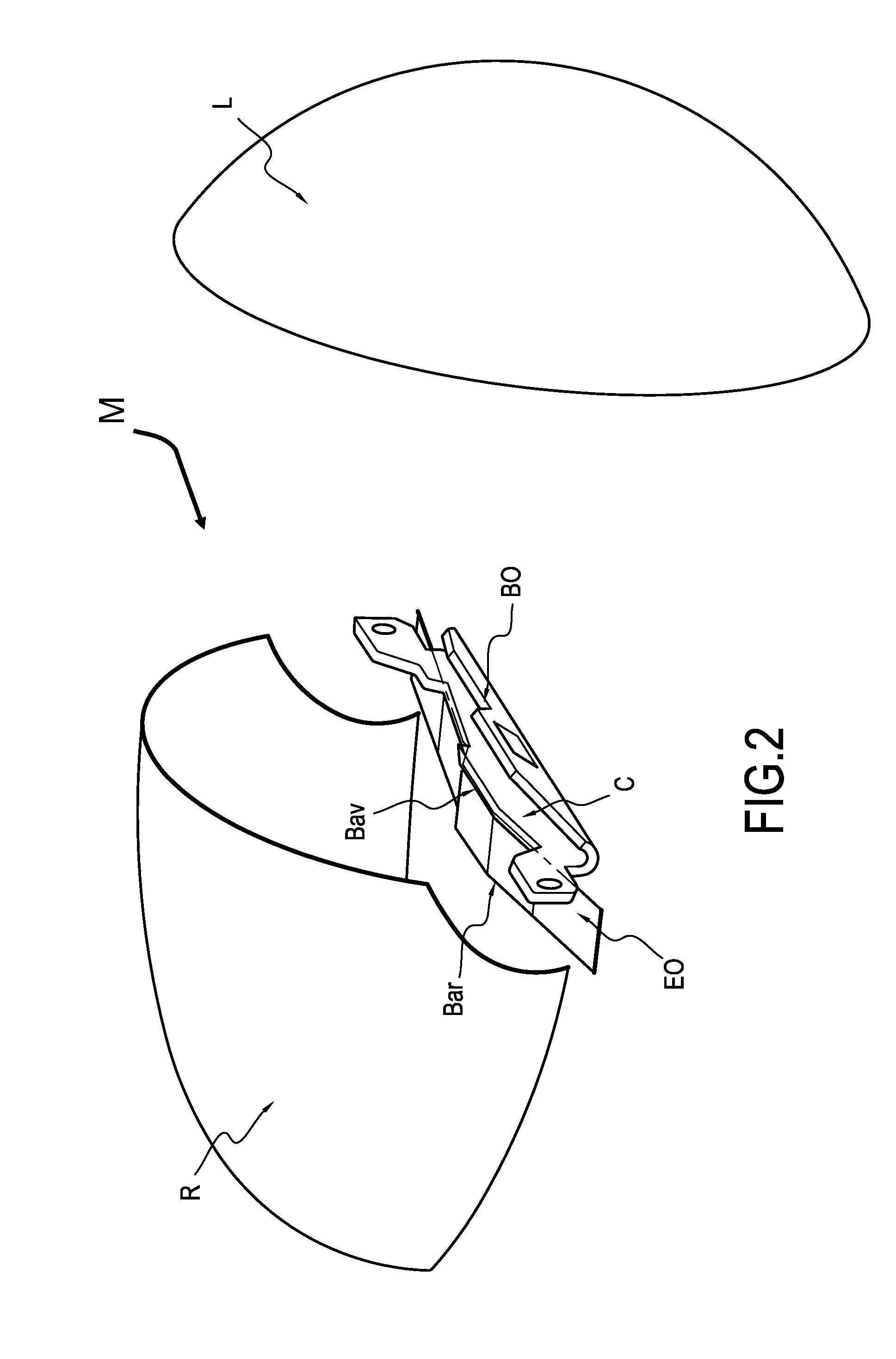
[0049]FIGS. 1 and 2 show the various main elements making up the optical module M according to the invention. The module comprises:

[0050] a reflector R, of which the geometrical shape of the reflective wall turned towards the front is close to a semi-ellipsoid. The figure depicts a reflector truncated in its lower part. An alternative is to use a “complete” reflector, the shape of which would be close to a complete ellipsoid;

[0051] a light source S, not depicted, disposed at the back of the reflector R in a known manner. This can be a halogen bulb, a xenon bulb, or one or more light-emitting diodes. For example, it is a halogen bulb, which is situated at the internal focus of the reflector;

[0052] a dioptric element, such as a convergent lens L (which can be of Fresnel type), which is situated at the second focus of the reflector;

[0053] a fixed shield C, whose optically active edge BO (FIG. 2) is the mar...


PUM


Abstract

An optical module for a motor vehicle lighting device, capable of emitting at least one type of light beam having a cut-off and comprising: a light source disposed in a reflector; a dioptric element, in particular a convergent lens, disposed in front of the reflector; a shield disposed between said light source and said dioptric element; and an additional optical element is disposed between the light source and the shield.

Description

BACKGROUND OF THE INVENTION [0001] 1. Field of the Invention [0002] The present invention relates to an optical module for a motor vehicle lighting device of the projector type and more particularly, to optical modules referred to as elliptical modules comprising a light source associated with a reflector and closed by a dioptric element of the convergent lens type, for example a plano-convex type lens, or a Fresnel lens. The invention provides optical modules equipped with a fixed or movable shield capable of intercepting at least partially, according to its position, the light beam emitted by the light source / reflector assembly. The shape of the upper edge of the shield makes it possible to delimit the desired cut-off in the beam by imagery with the convergent lens. [0003] 2. Description of the Related Art [0004] Besides these well-known lighting and signalling functions, new functions have recently appeared, grouped together under the name AFS (Advanced Front System), which offer...

Claims


Application Information

Patent Timeline
Patent Type & Authority Applications(United States)
IPC IPC(8): F21V7/00F21W107/10
CPCF21S48/1388F21S48/1768F21S48/145F21S41/321F21S41/337F21S41/43F21S41/683F21S41/365
Inventor MEYRENAUD, JEAN-LUC
Owner VALEO VISION SA
Why Eureka
Try Eureka