Acoustic design support apparatus

a technology for acoustic design and support apparatus, which is applied in the direction of transducer details, instruments, electrical transducers, etc., can solve the problems of not being suitable for design, taking a lot of calculation time, and designing angle conditions of speakers, so as to reduce the adjustment at the site, improve the simulation speed, and reduce the design process.

Inactive Publication Date: 2007-01-25
YAMAHA CORP
View PDF7 Cites 30 Cited by
  • Summary
  • Abstract
  • Description
  • Claims
  • Application Information

AI Technical Summary

Benefits of technology

[0020] Therefore, the present invention has been made in view of the above problems, and it is an object of the present invention to automate condition setting of an acoustic design support apparatus and program and also to increase the speed of simulation, thereby achieving an efficient and reduced design process and also reducing adjustment at the site.

Problems solved by technology

Thus, designers themselves must repeat such simulations by trial and error to obtain optimal directions of speakers, so that they usually have trouble in designing angle conditions of speakers.
Thus, to align time axes of various data, it is necessary to perform a plurality of FFT or inverse FFT calculations in a process of calculating the variety of acoustic parameters, thus taking a lot of calculation time.
For this reason, this method is not suitable for design that requires a lot of trial and error taking into consideration a variety of combinations of dispositions of speakers.
This increases the calculation time of FFT, which takes a lot of calculation time, since the amount of data to be FFTed is increased.
Although there are such specific speaker shapes, the above patent references do not provide any specific suggestion or description about how to optimize mounting angles of the array speaker and angles between the speaker units in order to make uniform the frequency characteristics of sound pressure levels of the sound receiving surface or the distribution of the sound pressure levels.
In the related art, there is no technology for easily and automatically presenting and arranging detailed options of speakers suitable for the space shape information.
In the related art, there is no technology for automatically displaying an easy-to-see three-dimensional disposition of the speaker in the space.
It is not easy to collect the CAD data.

Method used


Image

  • Acoustic design support apparatus
  • Acoustic design support apparatus
  • Acoustic design support apparatus

Examples


Embodiment Construction

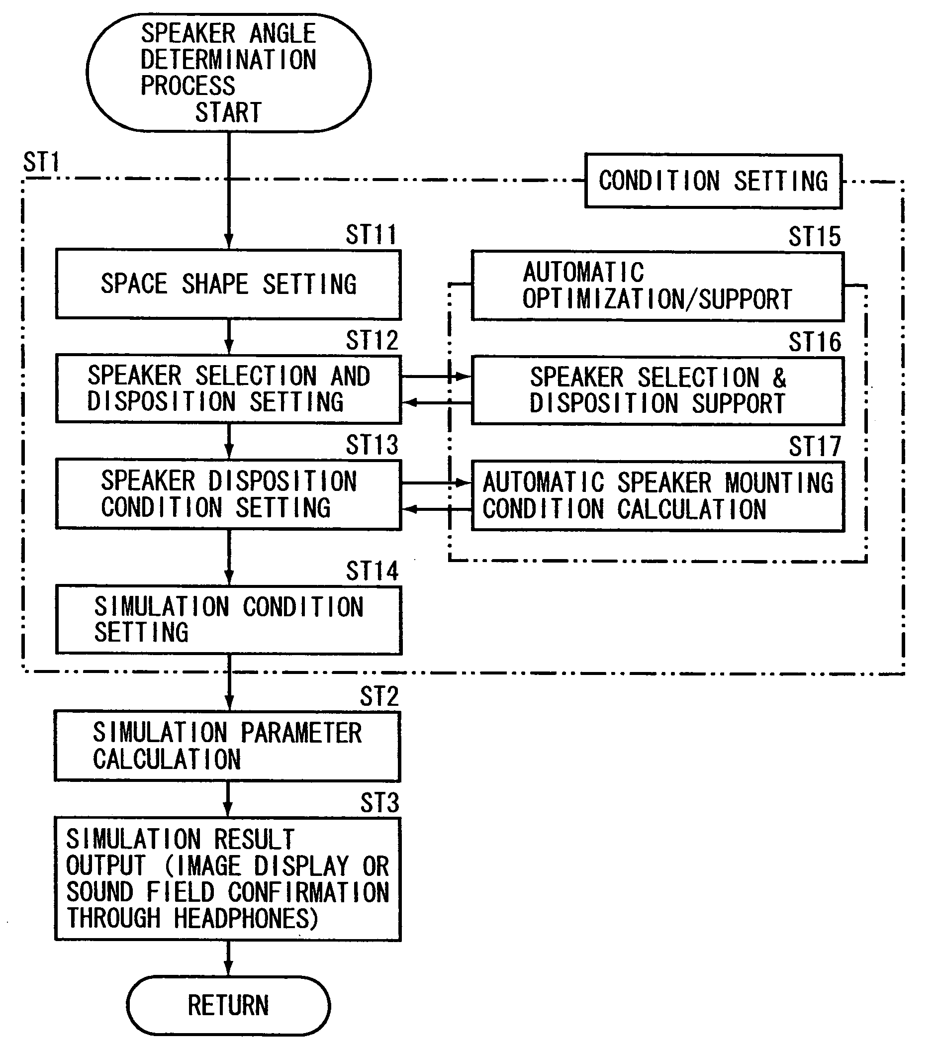
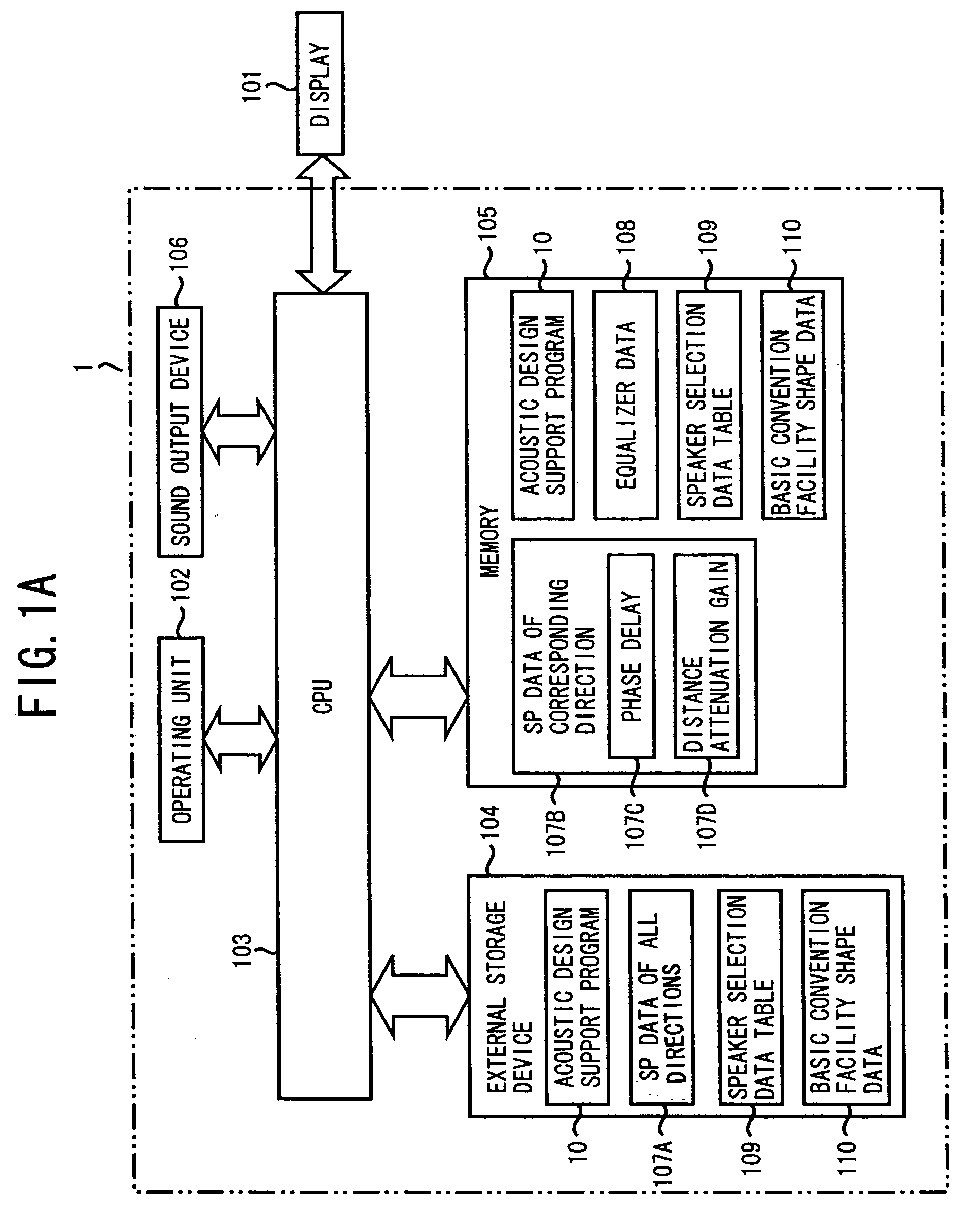
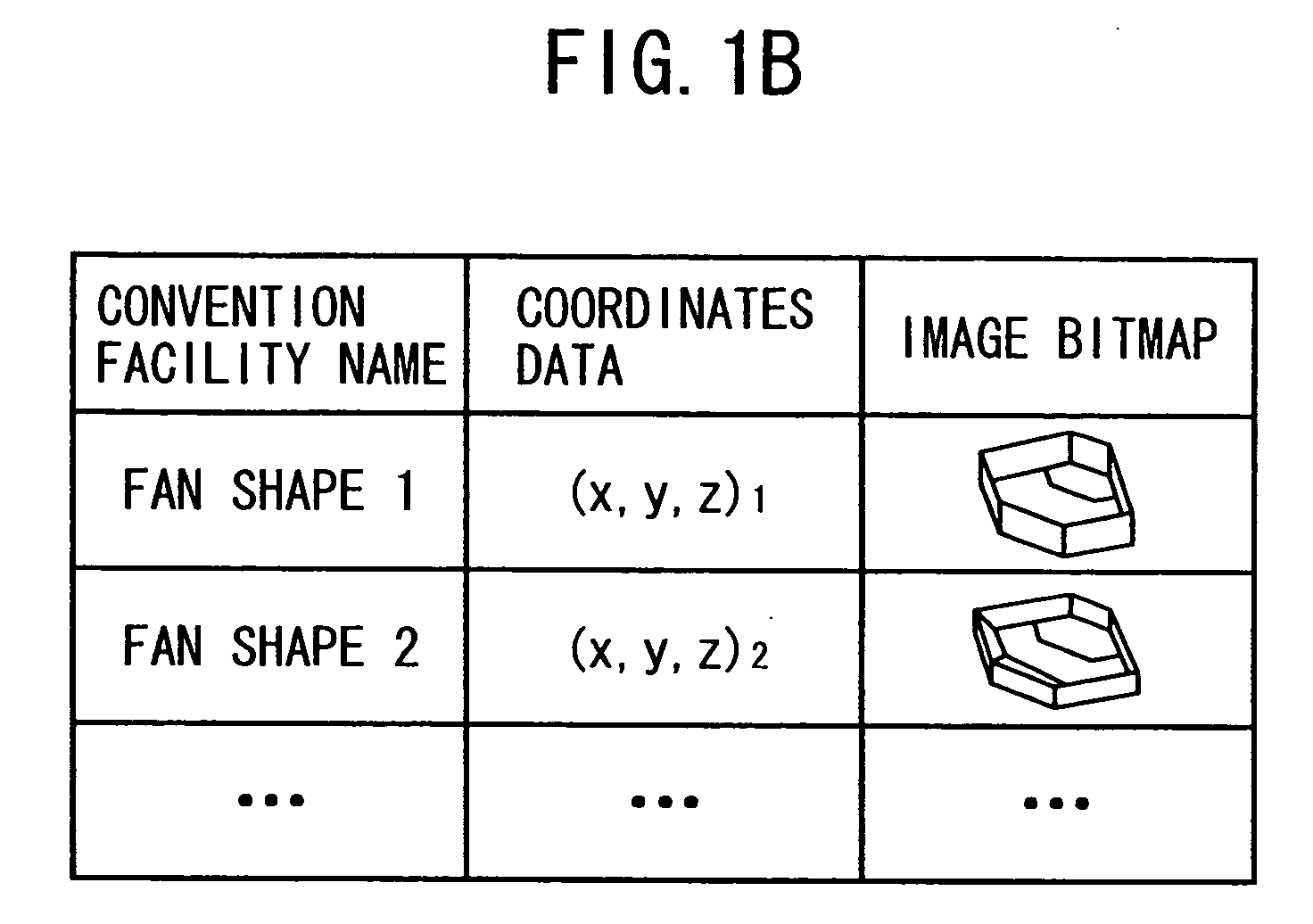
[0059] An internal configuration of an acoustic design support apparatus according to an embodiment of the present invention will now be described with reference to FIG. 1. FIG. 1 illustrates an internal configuration of an acoustic design support apparatus and a data structure of data of basic convention facility shapes in this embodiment. The acoustic design support apparatus 1 supports selection or setting of acoustic equipment such as a speaker in a convention facility such as a hall or a conference center. The acoustic design support apparatus 1 simulates a sound field when a sound is output and displays the simulation results. As shown in FIG. 1A, the acoustic design support apparatus 1 includes a computer or the like and a program installed on the computer or stored in a fixed memory. Specifically, the acoustic design support apparatus 1 includes an operating unit 102, a CPU 103, an external storage device 104, a memory 105, and an audio output device 106, and outputs simulat...


PUM


Abstract

In an acoustic design support apparatus, a speaker selection supporter selects a desired speaker as a candidate for use in a given space based on shape information representing a shape of the space. A speaker mounting angle optimizer calculates an optimal mounting direction of the selected speaker by selecting a mounting direction pattern which minimizes a degree of variation among sound pressure levels at a plurality of positions on a sound receiving surface defined in the space. An acoustic parameter calculator calculates a variety of acoustic parameters at sound receiving points within the space based on both of the shape information of the space and the optimal mounting direction of the speaker.

Description

BACKGROUND OF THE INVENTION [0001] 1. Technical Field of the Invention [0002] The present invention relates to an apparatus and program for supporting acoustic design of acoustic facilities. [0003] 2. Description of the Related Art [0004] A variety of design support apparatuses or programs have been suggested for use in designing acoustic equipment in a convention facility such as a music hall or a conference center (see Patent References 1-4). These apparatuses or programs preferably display acoustic characteristics of a speaker sound receiving surface or a sound receiving surface for short, where seats or the like receiving sounds from speakers mounted in a music hall or the like are positioned, on a display device based on characteristics of a selected acoustic system before installing the acoustic equipment at the site so that the displayed acoustic characteristics can be reflected in selection of the acoustic system or in acoustic adjustment of the site. [0005] Patent Reference...

Claims


Application Information

Patent Timeline
Patent Type & Authority Applications(United States)
IPC IPC(8): H04R1/02
CPCH04S7/301H04S7/307H04S7/302
Inventor MIYAZAKI, HIDEOWATANABE, TAKAYUKISAKANASHI, HIDEKIMATSUMOTO, SHUICHI
Owner YAMAHA CORP
Why Eureka
Try Eureka