Mechanical ship lift

a technology for lifting ships and mechanical devices, applied in vertical ship lifting, climate change adaptation, construction, etc., can solve problems such as adding to their cost, and achieve the effect of low power consumption

Inactive Publication Date: 2007-01-25
SHELTON BERT G
View PDF1 Cites 13 Cited by
  • Summary
  • Abstract
  • Description
  • Claims
  • Application Information

AI Technical Summary

Benefits of technology

[0015] The counter-balanced Shelton mechanical ship lift simultaneously raises and lowers ships, yet expels a relatively small volume of water in the process. The device operates using significantly low amounts of power as compared to other comparable ship lifts. Because the device moves ships in both direction

Problems solved by technology

Thus, the watershed will be enlarged in order to op

Method used


Image

  • Mechanical ship lift
  • Mechanical ship lift
  • Mechanical ship lift

Examples


Embodiment Construction

[0030] For the purposes of promoting an understanding of the principles of the invention, reference will now be made to the embodiment illustrated in the drawings and specific language will be used to describe the same. It will nevertheless be understood that no limitation of the scope of the invention is thereby intended, such alterations and further modifications in the illustrated device, and such further applications of the principles of the invention as illustrated therein being contemplated as would normally occur to one skilled in the art to which the invention relates.

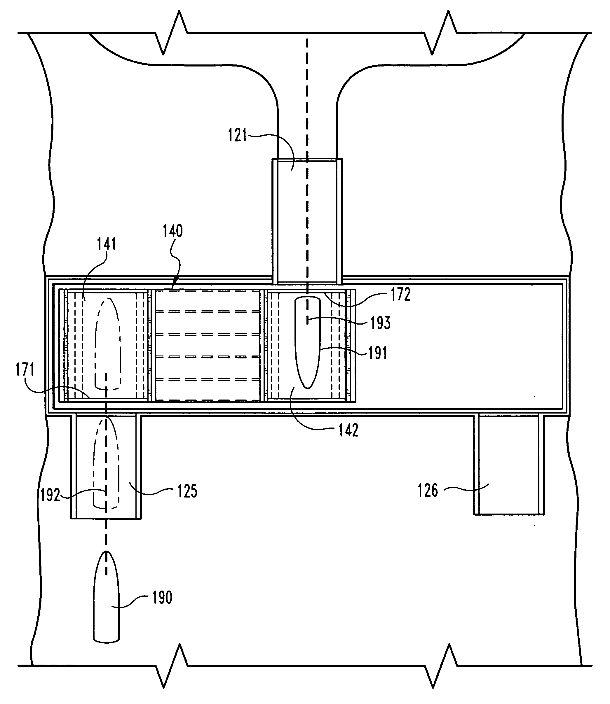
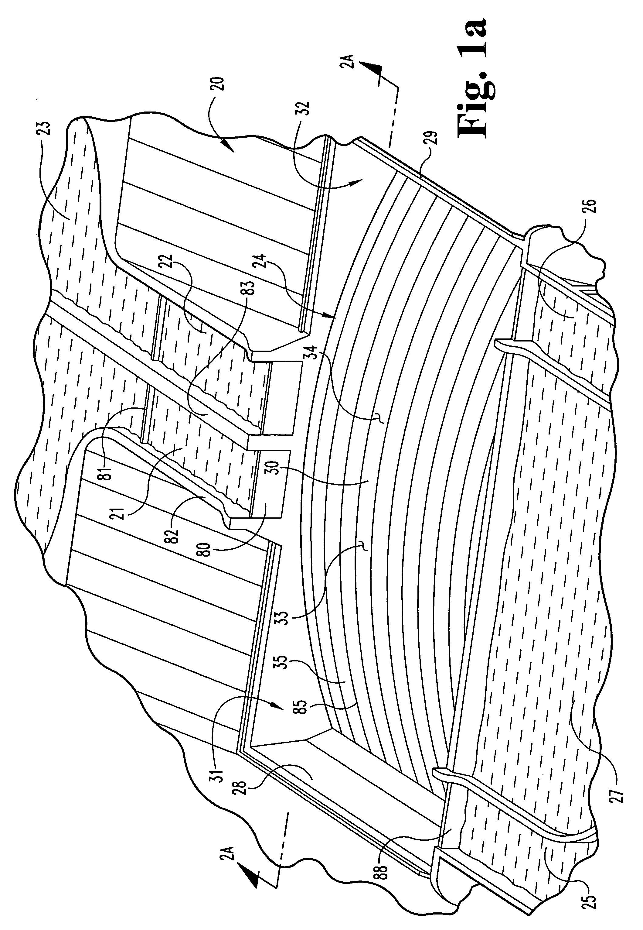
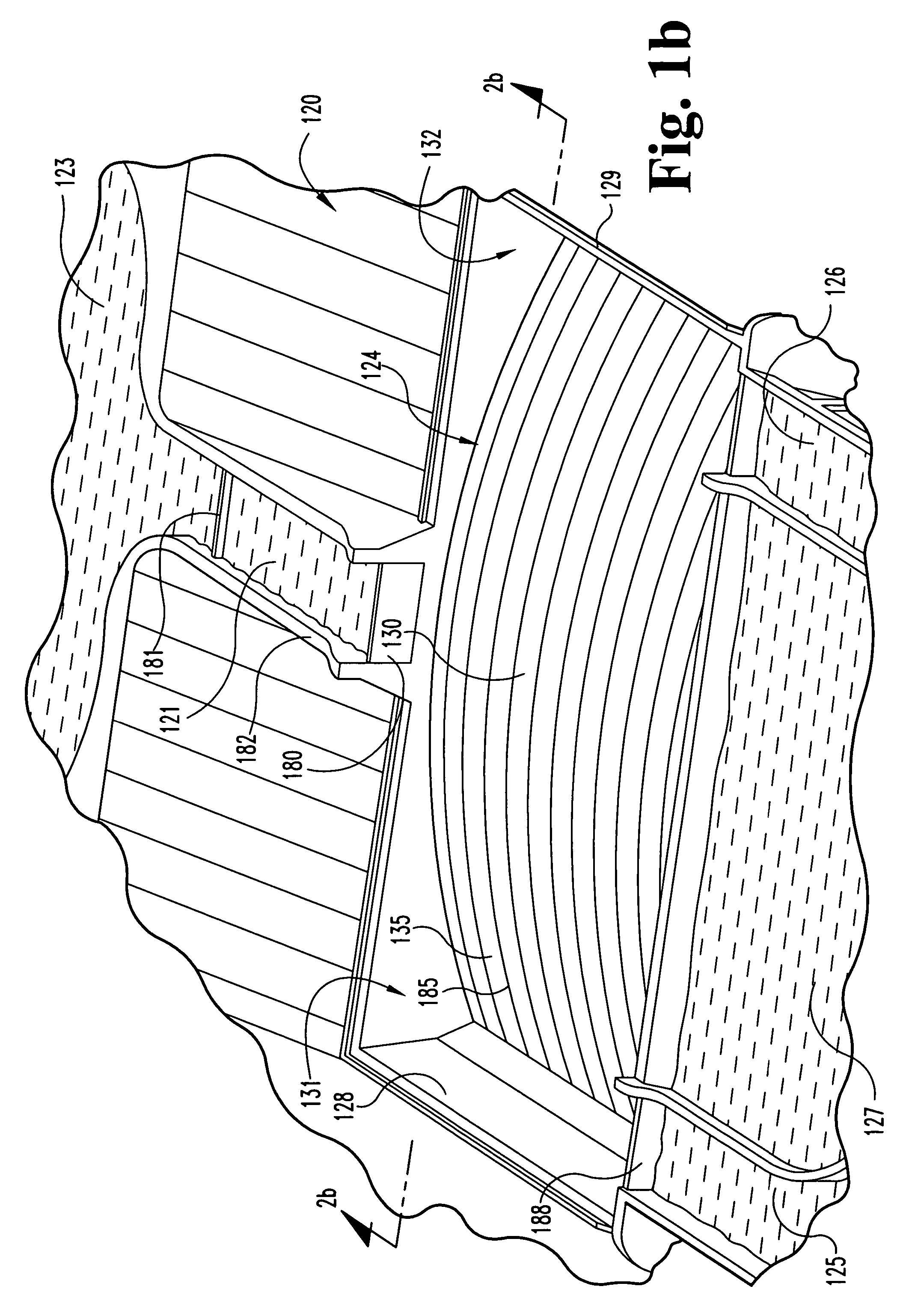
[0031] The SSL, disclosed herein, is well suited for the biggest of ships. My ship lift, consisting of two chambers rigidly connected by beams, moves about a fixed axis-of-rotation, but not about the complete circle and not with the chambers at opposite sides of the circle. The SSL's symmetrical chamber pair moves, or translates, along a relatively short arc of a very big circle, an arc that can be simply desc...


PUM


Abstract

A system for lifting ships from one waterway to another waterway. A convex basin is constructed between the waterways and slidably receives a pair of inter-connected chambers movable transverse to the direction of the waterway.

Description

BACKGROUND OF THE INVENTION [0001] 1. Field of the Invention [0002] The present invention relates generally to the field of devices for lifting ships including canal locks and mechanical lifting devices. [0003] 2. Description of the Prior Art [0004] As an example of a common method of lifting ships, one merely has to consider the design of the Panama Canal. Today's Panama Canal operates conventional locks raising ships three steps from one ocean to a lake then lowering them three steps again to the other ocean. Typical operation of the present day locks releases about 85 thousand cubic meters (22.4 million gallons) of fresh water to the sea each to raise and then to lower a ship. Based on a Year 2003 reported average of 38 ship transits per day, about 3.23 million cubic meters (1.7 billion gallons) of fresh water were used per day that year. [0005] During the tropical rainy season, the present Panama Canal typically receives sufficient water to permit the highest throughput of ships...

Claims


Application Information

Patent Timeline
IPC IPC(8): E02C1/00E02C5/00
CPCE02C5/00E02C1/00Y02A10/30
Inventor SHELTON, BERT G.
Owner SHELTON BERT G
Why Eureka
Try Eureka