Vehicle suspension control system and method

a technology for suspension control and vehicle suspension, applied in the direction of shock absorbers, instruments, cycle equipment, etc., can solve the problems of jolting not being reduced, the wheel riding up over a change in level, etc., and achieve the effect of reducing jolting

Inactive Publication Date: 2007-01-25
AISIN AW CO LTD
View PDF19 Cites 55 Cited by
  • Summary
  • Abstract
  • Description
  • Claims
  • Application Information

AI Technical Summary

Benefits of technology

[0007] It is an object of the present invention to solve the problems of the conventional vehicle suspension control system so as to provide a vehicle suspension control (“ride-up control”) system and suspension control method that can reliably reduce the jolting sensation when a vehicle wheel rides up over a change in level.
[0009] According to the present invention, because the system judges whether or not a wheel will ride-up over the change in level is predicted, based on the predicted travel path, and controls the operation of the vehicle suspension mechanism when wheel ride-up over the change in level is predicted, the system can reliably reduce jolting.

Problems solved by technology

For example, when a vehicle is traveling a narrow roadway and the driver attempts to turn the vehicle left or right at an intersection or the like that has an irregular conformation, a failure to start the turn at the right point, a difference in tracking between the front and rear inside wheels, or another such factor may result in a wheel riding up over a change in level located between the roadway and the sidewalk at the side of the road.
In these cases, often only one wheel rides up and over the change in level, and the jolting cannot be reduced.

Method used


Image

  • Vehicle suspension control system and method
  • Vehicle suspension control system and method
  • Vehicle suspension control system and method

Examples


first embodiment

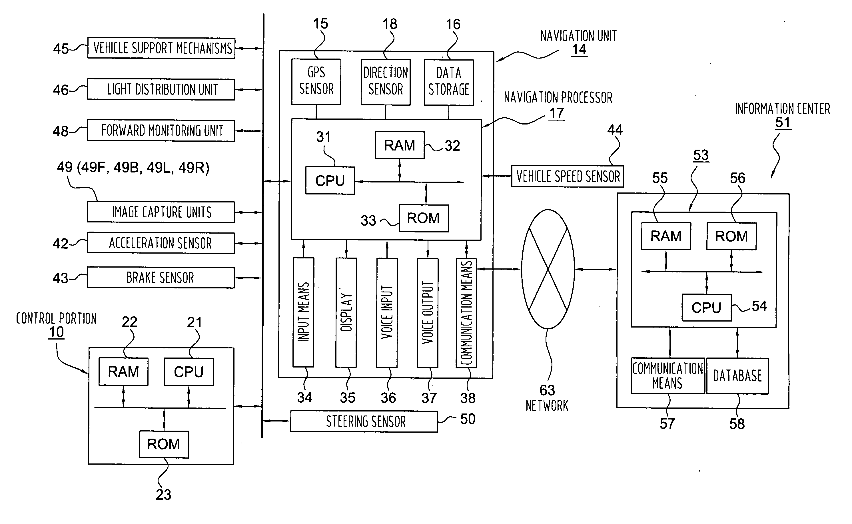
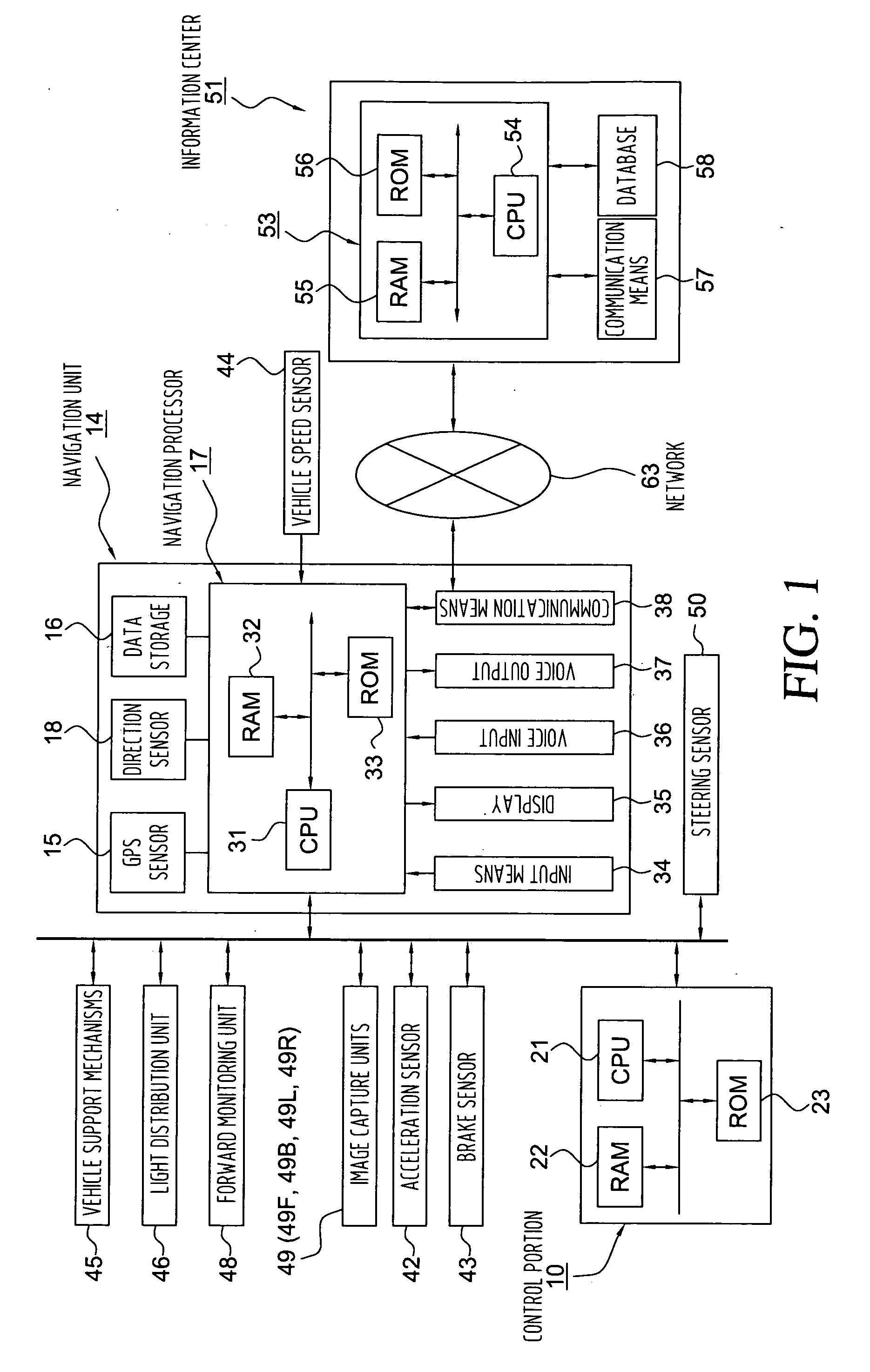
[0023]FIG. 1 shows the present invention as including a transmission control unit 10 which controls a power train that changes between prescribed gear ratios, such as a continuously variable transmission (CVT), an automatic transmission, an electric drive unit, or the like. The control section 10 includes a CPU 21 as a computation unit, as well as a RAM 22, a ROM 23, and a flash memory (not shown). The RAM 22 is used as working memory when the CPU 21 executes various types of computations. The ROM 23 contains a control program, as well as various other programs that search for routes to destinations, execute route guidance, and so on. The flash memory is used to store various types of data, programs, and the like.

[0024] The system of the first embodiment further includes, in addition to the control unit 10, an information terminal 14, i.e. “navigation unit”, that is installed in the host vehicle as an on-board unit, a network 63, and an information center 51 that serves as an inform...

second embodiment

[0091] Next, the present invention, which uses the navigation system, will be explained.

[0092]FIG. 11 is a flowchart of the operation of a suspension control system in accordance with the second embodiment of the present invention.

[0093] First, the suspension control section 70 determines whether or not matching processing has been executed. If matching processing has been executed, a road conformation (structure) acquisition section (not shown) of the suspension control section 70 executes road conformation acquisition. The road conformation acquisition section obtains the road conformation data for the vicinity of the host vehicle by reading the current position that was determined by the matching processing, then reading intersection data, road data, and the like from a data storage unit 16 (FIG. 1), which serves as an information storage unit. Note that where there is an intersection in the vicinity of the host vehicle, for example, the road conformation data that is obtained w...


PUM


Abstract

A vehicle suspension control system includes a level change recognition section that recognizes a change in level in a road, e.g. roadside curb, a travel path prediction section that predicts the travel path of the host vehicle, a ride-up judgment section which predicts that a wheel or wheels will ride up over the change in level, based on the predicted travel path, and a vehicle suspension element control section that controls the operation of the vehicle suspension or of an element thereof when ride up over the change in level is predicted. The system reliably reduces the jolting sensation which would otherwise occur when a wheel rides up over the change in level.

Description

INCORPORATION BY REFERENCE [0001] The disclosure of Japanese Patent Application No. 2005-214464 filed on Jul. 25, 2005, including the specification, drawings and abstract is incorporated herein by reference in its entirety. BACKGROUND OF THE INVENTION [0002] 1. Field of the Invention [0003] The present invention relates to a vehicle suspension control system and control method. [0004] 2. Description of the Related Art [0005] Conventionally, information on road conditions is obtained from map data and the like, and vehicle suspension characteristics are controlled according to the information obtained. For example, the vehicle control system disclosed in Japanese Patent Application Publication No. JP-A-2000-322695 is designed to reduce the jolting sensation that occurs when the vehicle passes over a change in the level of the road surface. [0006] However, with the conventional vehicle control system, the jolting sensation can be reduced only when information on road conditions can be...

Claims


Application Information

Patent Timeline
Patent Type & Authority Applications(United States)
IPC IPC(8): B60G17/018B60G17/056
CPCB60G17/019B60G2400/106B60G2400/204B60G2400/37B60G2401/28B60G2400/824B60G2401/142B60G2401/16B60G2400/40
Inventor MIYAJIMA, TAKAYUKI
Owner AISIN AW CO LTD
Why Eureka
Try Eureka