Load hoist arrangement

Inactive Publication Date: 2007-02-01
BINAR QUICK ELEVATOR SYST
View PDF6 Cites 14 Cited by
  • Summary
  • Abstract
  • Description
  • Claims
  • Application Information

AI Technical Summary

Benefits of technology

[0018] Preferably, said motors are capable of clockwise and counterclockwise turning, which in combination with the inventive pattern of the drag elem

Problems solved by technology

Since it is a dynamic system, often covering a large working area, and frequently used, the risk for play in the connections of t

Method used


Image

  • Load hoist arrangement
  • Load hoist arrangement
  • Load hoist arrangement

Examples


Example

[0028] A first embodiment of the invention related to a load hoist arrangement will be described in more detail in the following with reference to the accompanying drawings.

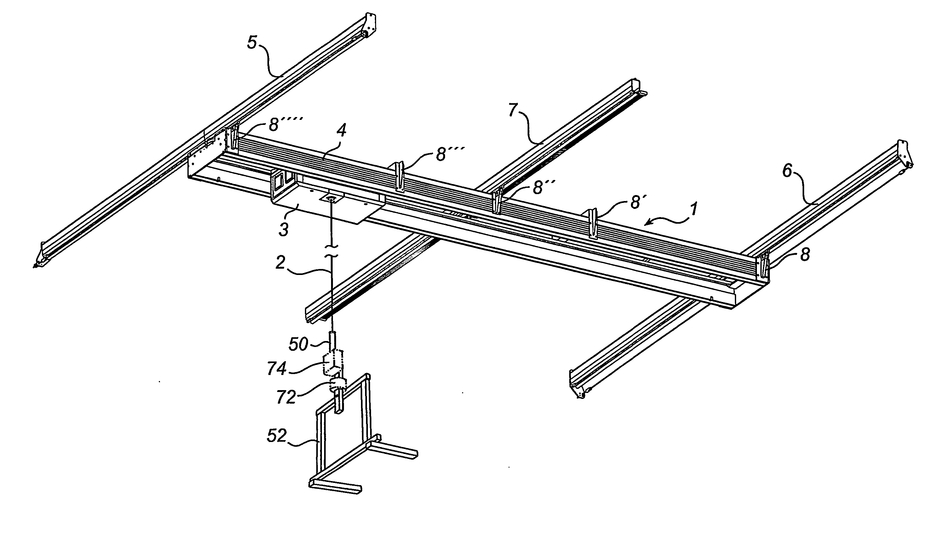
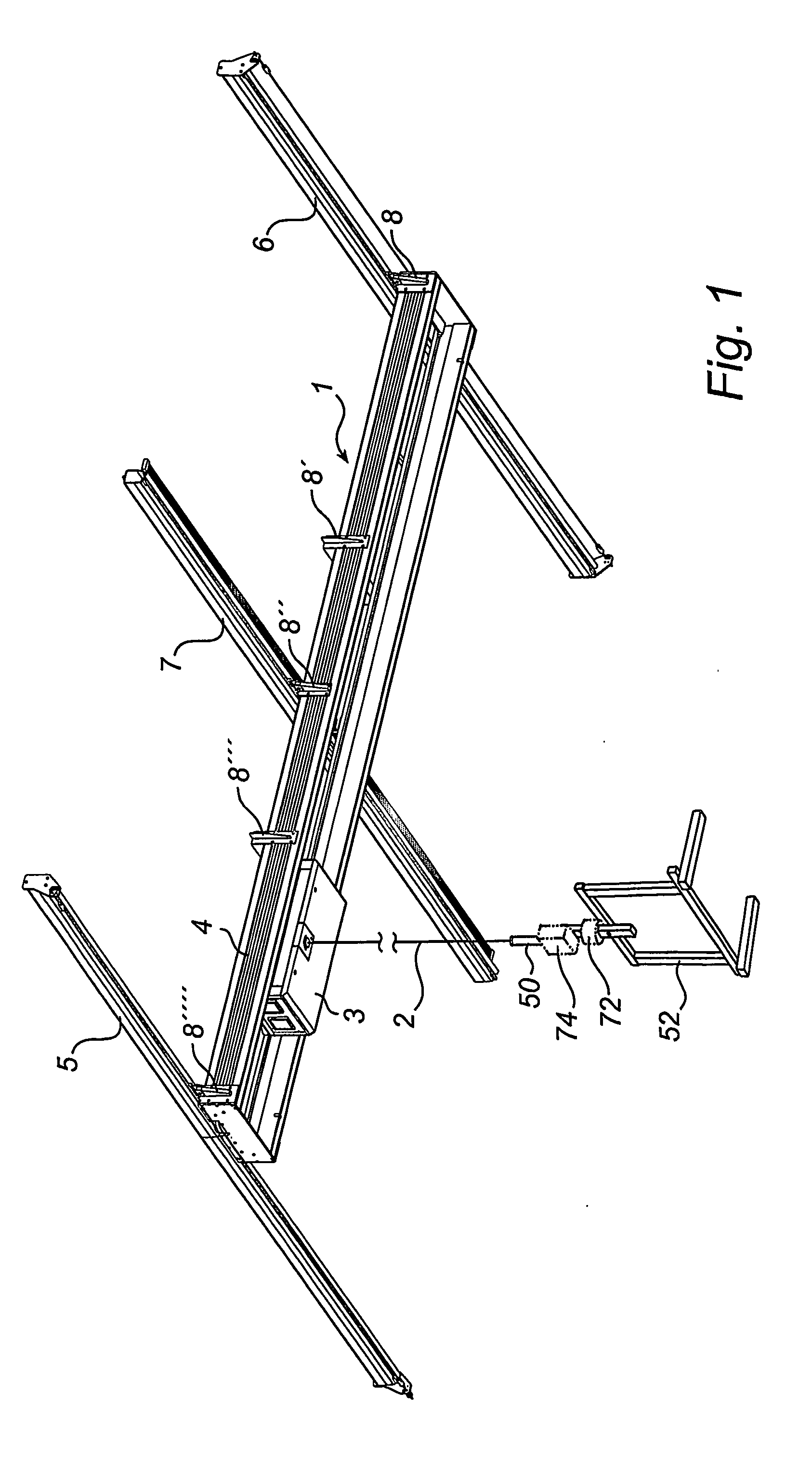
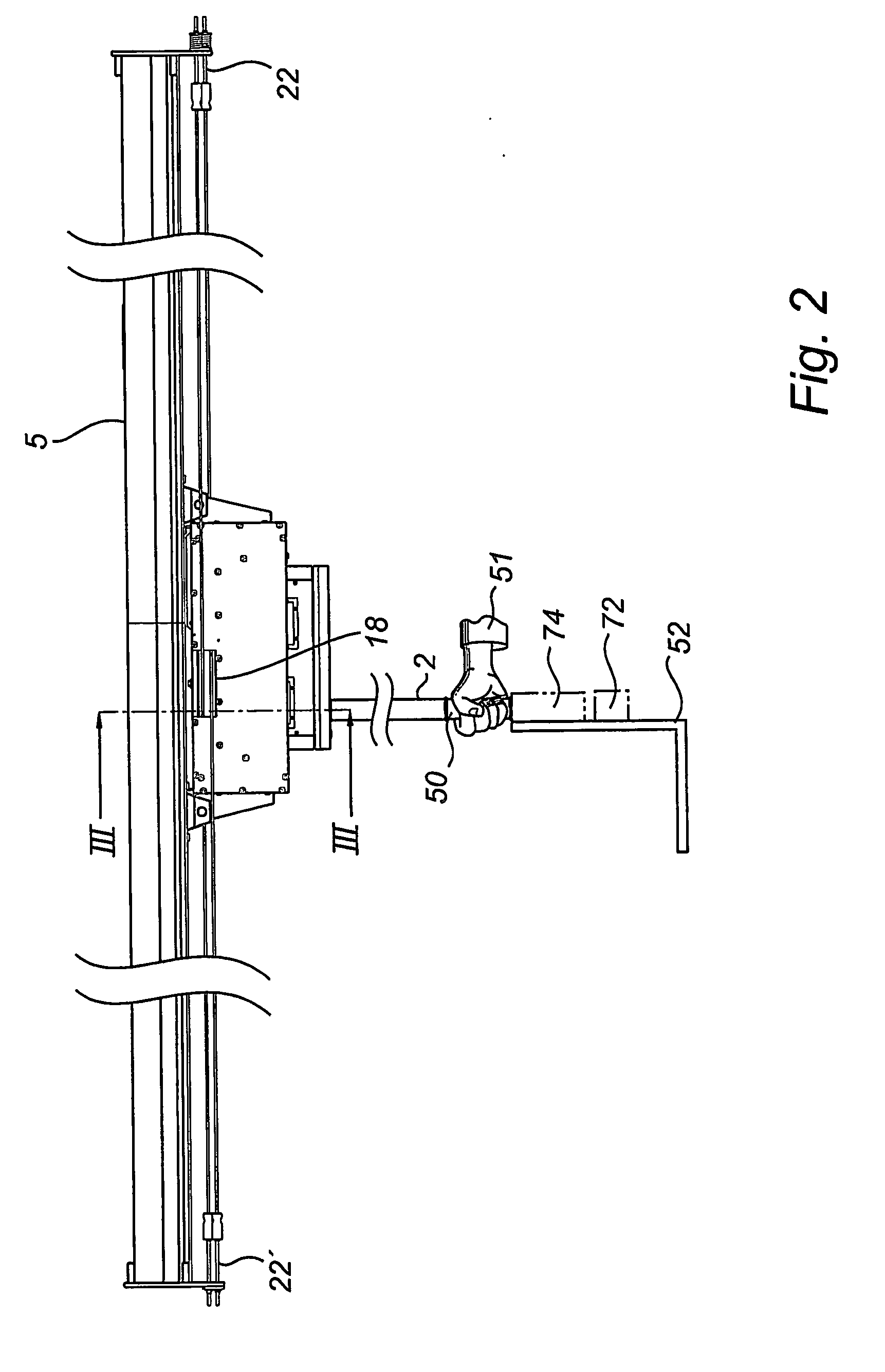
[0029] Referring now to FIG. 1, wherein a load hoist arrangement 1 according to the invention is shown. A control device 50 is arranged along a lifting cable 2 between a traverse device and a load carrying device 52. The load carrying device 52 is manually guidable in a three-dimensional space. Lateral movement of said load carrying device 52 is controlled by a driving device. The load carrying device 52, which is for example a hook, a magnet, a suction component etc., capable of being supported by a lifting cable 2. The driving device is controlled by recorded and transmitted force impacts from said control device 50 to said driving device.

[0030] Furthermore, said traverse device having support elements 5, 6, 7 for supporting a traveling bridge 4. The traveling bridge 4 is arranged to travel along said support...


PUM


Abstract

This invention relates to a load hoist arrangement (1) comprising a control device (50) arranged between a traverse device and a load carrying device (52). The load carrying device (52) is manually guidable in a three-dimentional space and lateral movement of said load carrying device (52) is controlled by a driving device. The driving device is controlled by recorded and transmitted force impacts from said control device (50) to said driving device. The traverse device has support elements (5, 6, 7) for supporting a traveling bridge (4), arranged to travel along said support elements (5, 6, 7), and a carriage (3) arranged to travel back and forth on said traveling bridge (4). The driving device comprises at least one motor, provided with at least two driving wheel units (15, 16), secured to said carriage (3) and two drag elements (21, 21′) secured at its end portions to opposite end portions of said support elements (5, 6) and crossing at said traveling bridge (4). The drag elements (21, 21′) crossing each other at said carriage (3) arranged such that a first driving wheel unit (15) works in contact with one drag element (21) and a second driving wheel unit (16) works in contact with another drag element (21′), thereby moving the carriage (3) and hence the load carrying device (52) in the lateral direction during operation.

Description

FIELD OF THE INVENTION [0001] The present invention relates to a load hoist arrangement comprising a control device arranged between a traverse device and a load carrying device, wherein said load carrying device is manually guidable in a three-dimensional space, and wherein lateral movement of said load carrying device is controlled by a driving device, said driving device is controlled by recorded and transmitted force impacts from said control device to said driving device, and wherein said traverse device having support elements for supporting a traveling bridge arranged to travel along said support elements and a carriage arranged to travel back and forth on said traveling bridge. TECHNICAL BACKGROUND [0002] There exist in the prior art an arrangement of the kind referred to above which permits the drive of the load carrying device to be influenced in the lateral sense through a lateral movement of a lifting cable. When lifting something using such prior art load hoist arrangem...

Claims


Application Information

Patent Timeline
IPC IPC(8): B66C19/00B66C13/18
CPCB66C13/18
Inventor KAHLMAN, STUREOLSSON, JOHAN
Owner BINAR QUICK ELEVATOR SYST
Why Eureka
Try Eureka