Rotating irradiation apparatus

Active Publication Date: 2007-02-01
HITACHI LTD
View PDF3 Cites 80 Cited by
  • Summary
  • Abstract
  • Description
  • Claims
  • Application Information

AI Technical Summary

Benefits of technology

[0017] Thus, the above rotating irradiation apparatus of the present invention is configured such that: the plurality of thrust support devices restrain the movement of the rotating body (or rotatable body) in the direction of its rotational axis; and the first rotating body support device or both the first and second rotating body support devices are movable in the direction of the rotational axis. This arrangement allows the movable rotating body support device or devices to be moved to accommodate the relative axial movement between the rotating body and the rollers supporting the rotating body due to misalignment between their axes. Therefore, the movement of the rotating body itself in the direction of its rotational axis is conside

Problems solved by technology

There is another factor in causing an error in the irradiation position.
This factor cannot be removed by increasing the rigidity of the rotating gantry body.
In reality, however, the rotational axes of the rollers of the radial support devices are not fully parallel to those of the front and rear rings due to the following factors: (a) errors in the machining and assembly of components of the rotating gantry; (b) adjustment errors during installation of the rotating gantry; (c) deterioration of the building with age; and (d) small variations in height, etc. due to wear of the rings and rollers.
Thus, there is a certain degree of misalignment between the rotational axes of the rollers and the rings.
As a result, the rotating gantry itself moves in the axial direction or a horizontal direction as it rotates, resulting in increased three-dimensional whirling of the irradiation position.
With this method, however, the thrust support devices receive large reactive force, making it necessary to considerably increase their rigidity.
Furthermore, the larger the axial thrust force applied by the thrust support devices, the larger the friction between the rings of the rotating gantry and the thrust rollers of the thrust support devices and

Method used


Image

  • Rotating irradiation apparatus
  • Rotating irradiation apparatus
  • Rotating irradiation apparatus

Examples


first embodiment

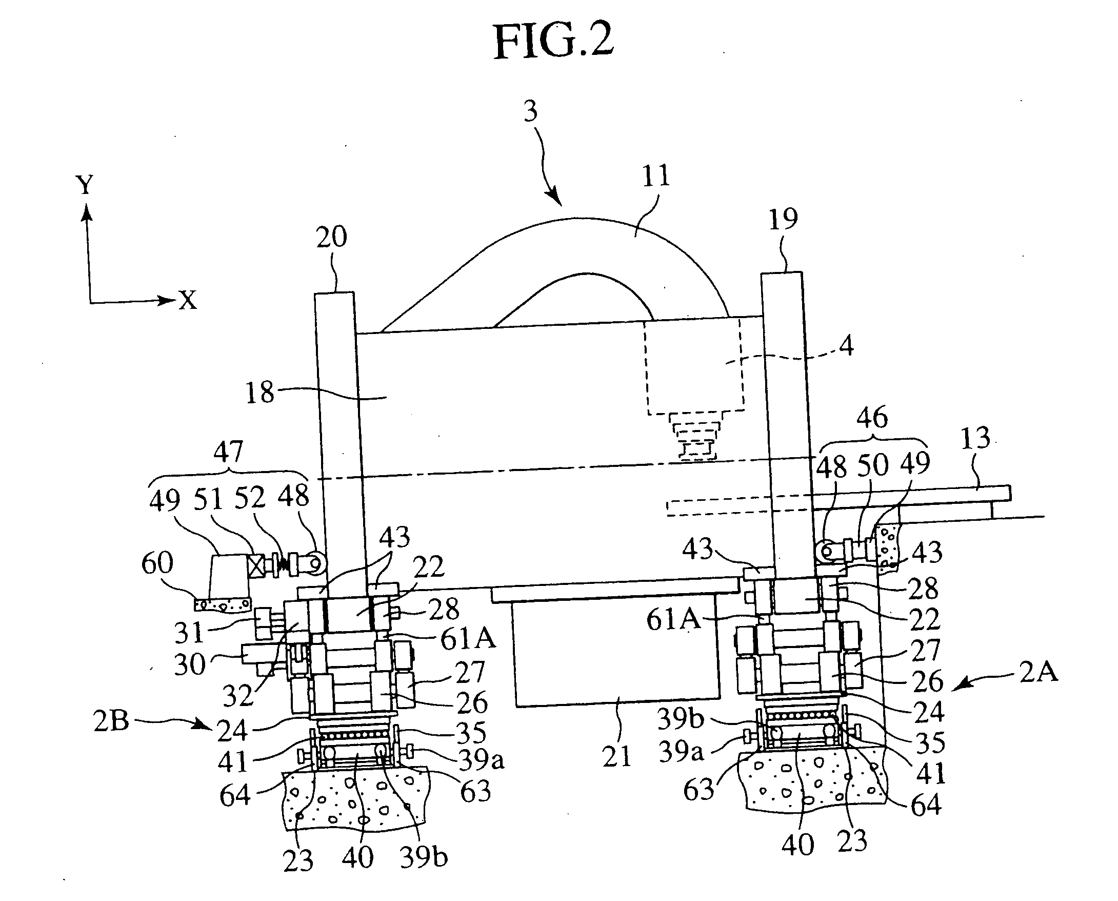
[0032] A rotating irradiation apparatus according to a first embodiment of the present invention will be described with reference to FIGS. 2 to 6A and 6B. The rotating irradiation apparatus of the first embodiment is a structure included in a particle radiotherapy system (or ion beam irradiation system). The rotating irradiation apparatus includes a rotating gantry 3, rotating body support devices 2A and 2B, an irradiation device 4, a beam delivery device 11, a motor (a rotational drive device) 30, a front thrust support device 46, and a rear thrust support device 47. The rotating gantry 3 includes a cylindrical gantry body 18, a front ring (a first annular member) 19 provided on the front end portion of the gantry body 18, and a rear ring (a second annular member) 20 provided on the rear end portion of the gantry body 18. Thus, the front ring 19 is disposed on the side from which a treatment table 13 is inserted into the treatment chamber (not shown) formed within the gantry body 1...

second embodiment

[0072] A rotating irradiation apparatus according to a second embodiment of the present invention will be described with reference to FIG. 7. The rotating irradiation apparatus of the second embodiment is a variation of the rotating irradiation apparatus of the first embodiment, in which the rotating gantry 3 is replaced by a rotating gantry 3A. All other components are similar to those described in connection with the first embodiment. The rotating gantry 3A includes a gantry body 18A and a front ring 19 and a rear ring 20 provided on respective ends of the gantry body 18A. Unlike the gantry body 18 of the first embodiment, the gantry body 18A has a truss structure. Since the gantry body 18A has a truss structure, it has lower rigidity but lighter weight than the gantry body 18. Since the gantry body 18A has lighter weight, the size of the rotating body support devices 2A and 2B can be reduced.

[0073] This embodiment also has the effects described in (1) to (12) above in connection...

third embodiment

[0074] A rotating irradiation apparatus according to a third embodiment of the present invention will be described with reference to FIGS. 8 and 9. The rotating irradiation apparatus of the third embodiment is a variation of the rotating irradiation apparatus of the first embodiment, in which the rotating body support devices 2A and 2B are replaced by rotating body support devices 2C and 2D. All other components are similar to those described in connection with the first embodiment. The rotating body support devices 2C and 2D include a radial support device 61C shown in FIG. 8 and a radial support device 61D not shown in FIG. 8, respectively. The radial support device 61C is disposed at the same position as the radial support device 61A shown in FIGS. 3 and 4, while the radial support device 61D is disposed at the same position as the radial support device 61B shown in FIGS. 3 and 4. Unlike the radial support devices 61A and 61B, the radial support devices 61C and 61D include roller...


PUM


Abstract

A rotating irradiation apparatus includes a rotating gantry 3 including a front ring 19 and a rear ring 20 and is provided with a beam delivery device 11 and an irradiation device 4. The beam delivery device 11 delivers an ion beam used for particle radiotherapy. Radial support devices 61A and 61B support the front ring 19 and radial support devices 61A and 61B support the rear ring 20. Each radial support device includes a linear guide 41, an upper support structure disposed above the linear guide 41, and a lower support structure disposed below the linear guide 41. The upper support structure is movably mounted on the lower support structure and is movable in the direction of the rotational axis of the rotating gantry 3.

Description

BACKGROUND OF THE INVENTION [0001] The present invention relates to a rotating irradiation apparatus, and more particularly to a rotating irradiation apparatus suitable for irradiating an affected area with an ion beam. [0002] An ion beam irradiation system is a particle radiotherapy system used to irradiate an affected area with a proton beam or an ion beam of carbon ions, etc. to treat cancer. The ion beam irradiation system includes a rotating gantry, which is a rotating irradiation device. For example, the rotating gantry includes a front ring, a rear ring, and a gantry body connected between the front and rear rings, as indicated in Japanese Patent Laid-open No. 11-47287. The gantry body is provided with an irradiation device (or irradiation nozzle) and a beam delivery device (or beam path) for guiding an ion beam. The front and rear rings are supported by their respective radial support devices each including a plurality of rotatable rollers. More specifically, each roller pro...

Claims


Application Information

Patent Timeline
IPC IPC(8): H01J37/08
CPCA61N5/10A61N2005/1087A61N5/1081
Inventor YAMASHITA, TSUTOMUKANEKO, SHIGEJISAGA, HIROSHITAKEDA, NORIO
Owner HITACHI LTD
Why Eureka
Try Eureka