Chuck

a technology of chuck and chuck body, which is applied in the field of chuck, can solve the problems of high impact stress, wear and fatigue, and achieve the effect of high strength

Inactive Publication Date: 2007-02-01
HILTI AG
View PDF20 Cites 32 Cited by
  • Summary
  • Abstract
  • Description
  • Claims
  • Application Information

AI Technical Summary

Benefits of technology

[0021] Advantageously, the outer part of the locking means is fo

Problems solved by technology

Generally, in connection with the use of the chucks in power hand-held tools, within the chuck, high-impact stresses are produced as

Method used


Image

  • Chuck
  • Chuck

Examples


Embodiment Construction

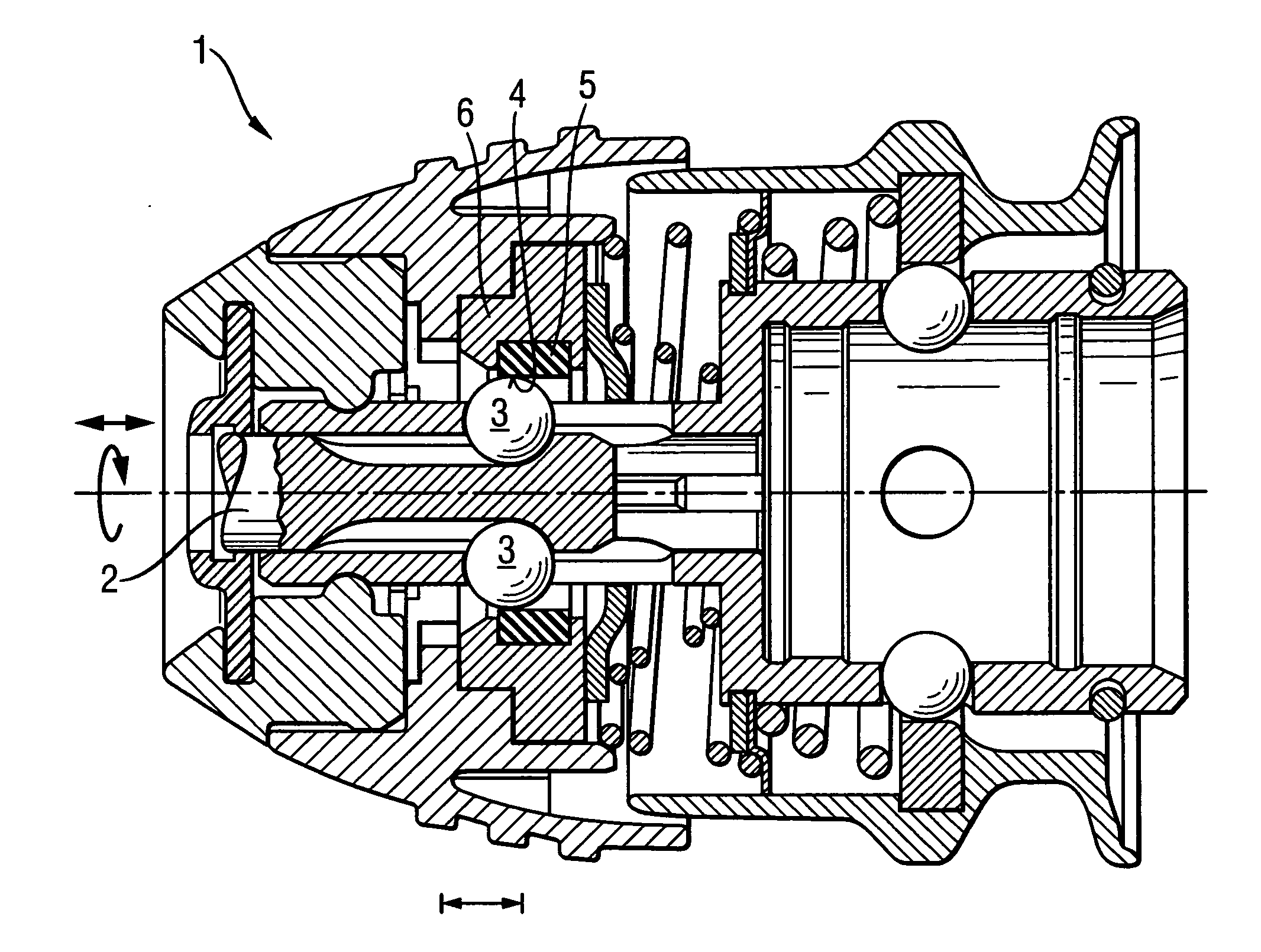
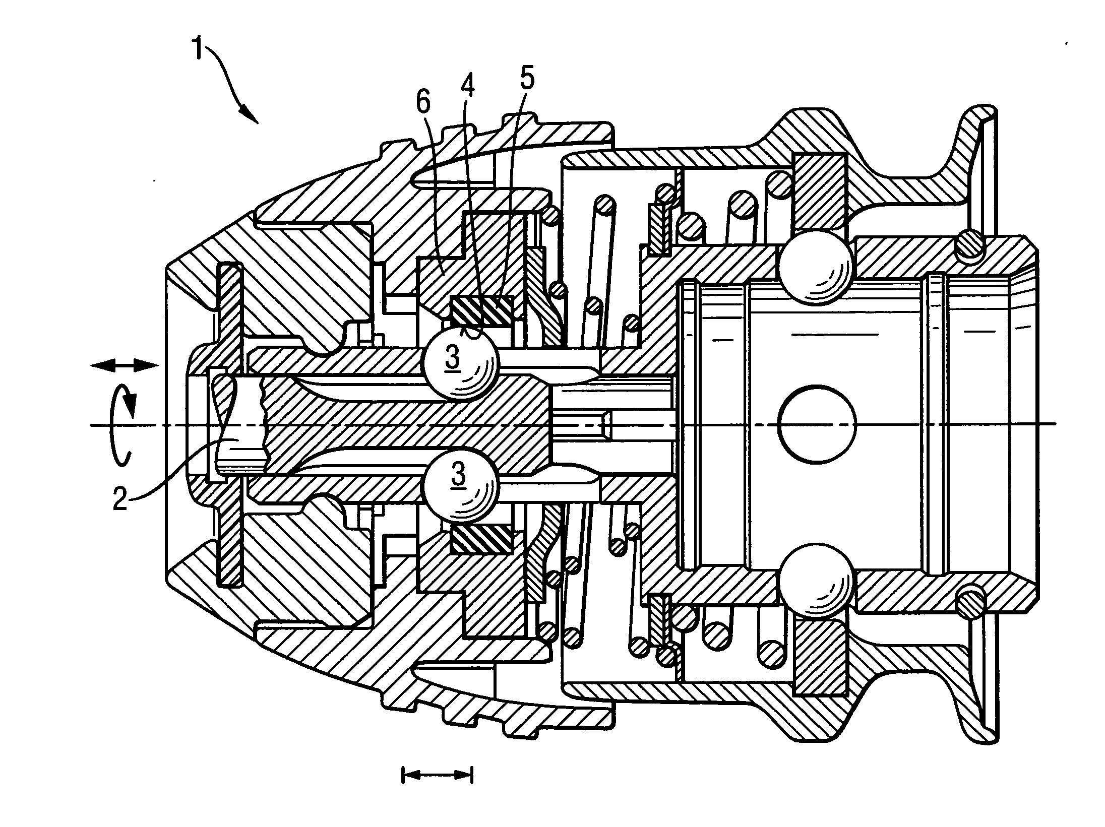
[0025] A chuck 1 according to the present invention, which is shown in the drawing, is designed for receiving a shank 2, shown only partially, of a percussively driven working tool. The chuck 1 has two radially displaceable locking members 3 in the form of balls. An approximately circular locking element 5-6, which is manually axially displaceable from outside, blocks radial displacement of the locking balls outwardly and has a locking surface 43 which is located radially adjacent to the locking members 3. The locking element 5-6 is formed of two parts made of different materials. The inner part 5 forms a locking surface 4. The outer, axially displaceable part 6 is made of metal. The radial thickness of the damping ring, which is formed of elastic silicone resin with Shore A hardness of 90, with a maximum of loss modulus at 50° and 10 Hz, amounting to a third of a radial extent of the locking balls.

[0026] Though the present invention was shown and described with references to the p...


PUM


Abstract

A chuck for a percussively driven working tool includes at least one radially displaceable, locking member (3) and a locking element (5, 6) for blocking radial displacement the at least one locking member outwardly. The locking member has a locking surface (4) located radially adjacent to the at least one locking member (3) and formed as a radially damping surface.

Description

BACKGROUND OF THE INVENTION [0001] 1. Field of the Invention [0002] The present invention relates to a chuck for a mechanized, at least partially percussively driven working tool such as chisel or percussion drill with a radially displaceable locking member. [0003] 2. Description of the Prior Art [0004] Chucks as described above have a radially displaceable locking member for radiallly engaging in a locking groove of a working tool shank, and locking means that blocks the displacement of the locking member radially outwardly. [0005] Generally, in connection with the use of the chucks in power hand-held tools, within the chuck, high-impact stresses are produced as a result of which separate parts such as locking members are subjected to complex vibrations that can lead to their wear and fatigue. [0006] As disclosed in U.S. Pat. No. 6,241,026, German publication DE 440 56 97, and U.S. publication US 2003 / 089509, such chucks include radially displaceable locking members and a locking r...

Claims


Application Information

Patent Timeline
IPC IPC(8): B23B31/16
CPCB25D17/088B25D17/24Y10T279/17752B25D2250/085B25D2217/0042
Inventor HAUPTMANN, UDOSPECHT, HELMUTLOEFFLER, ALEXANDER
Owner HILTI AG
Why Eureka
Try Eureka