Cab for construction machinery

a construction machinery and cab technology, applied in soil shifting machines/dredgers, roofs, transportation and packaging, etc., can solve the problems of increased cost, increased assembling process and therefore man-hour, poor productivity, etc., to reduce shock, improve rigidity of the rear part of the cab, and reduce the effect of assembling process

Inactive Publication Date: 2007-02-01
KOMATSU LTD
View PDF40 Cites 21 Cited by
  • Summary
  • Abstract
  • Description
  • Claims
  • Application Information

AI Technical Summary

Benefits of technology

[0013] According to claim 5, there is provided a cab for a construction machine, wherein the intermediate pillar 85 is connected to the right front pillar 14 or the right rear pillar 15 by passing through the ceiling portion. Effect of the Invention
[0014] In the cab for a construction machine according to claim 1, the cab can be protected from deformation, damage etc. caused by shocks from the outside by increasing the rigidity of the rear part of the cab. In addition, since there is no need to provide the construction machine with a protecting member or the like unintegral with the cab in order to mitigate shocks from the outside, the cab has good design. Further, since the front part of the cab does not need great rigidity, the cab can avoid a structure which interrupts the front field of view and therefore has improved front visibility. Further, since it is unnecessary to form the left front pillar and the right front pillar from a pipe material, cost reduction can be achieved.
[0015] In the cab for a construction machine according to claim 2, since the ceiling portion is supported by the right front pillar, the rigidity of the ceiling portion increases.
[0016] In the cab for a construction machine according to claim 3, since the left front pillar may be short in length, it can be easily formed by press molding and a wide entrance can be made.
[0017] In the cab for a construction machine according to claim 4, since a left side face portion is reinforced by the intermediate pillar, sufficient strength can be imparted to the left side face portion, even if an opening for the entrance is formed in the left side face portion, so that stable formation of the opening becomes possible.
[0018] In the cab for a construction machine according to claim 5, since the ceiling portion is supported by the intermediate pillar, the rigidity of the ceiling portion increases.

Problems solved by technology

The cabs having a framework made of pipe materials such as that of Patent Document 1, however, present the drawback that use of a number of pipe materials increases costs and use of a number of joints for coupling the pipe materials increases the number of assembling processes and therefore man-hour, which leads to poor productivity.
On the other hand, the cabs, which do not use a framework composed of pipe members such as that of Patent Document 2, do not cost much but is inferior in strength.
This attempt, however, has revealed the problem that the provision of the protecting member makes the design of the cab worse and increases the size of the cab.
To achieve increased rigidity in the front part of the cab, the front pillars (posts) need to be thickened, which leads to a decrease in front visibility.

Method used


Image

  • Cab for construction machinery
  • Cab for construction machinery
  • Cab for construction machinery

Examples


Embodiment Construction

[0040] Referring now to the accompanying drawings, a cab for a construction machine will be described in detail according to preferred embodiments of the invention. FIG. 3 schematically shows a hydraulic excavator of a construction machine. The hydraulic excavator has lower machinery 1 and upper structure 2 mounted on the lower machinery 1. The upper structure 2 has a driver's cabin (cab) 4 on its frame 3. The upper structure 2 further includes a work implement 8 or the like having a boom 5, an arm 6 and a bucket 7. When the terms “front side (foreside)”, “rear side” (opposite to the front side), “left side” and“right side” are used in this embodiment, it should be understood that these terms have reference to the structure of the construction machine as it would appear to the operator sitting on the driving seat (not shown) of the cab 4 of the construction machine.

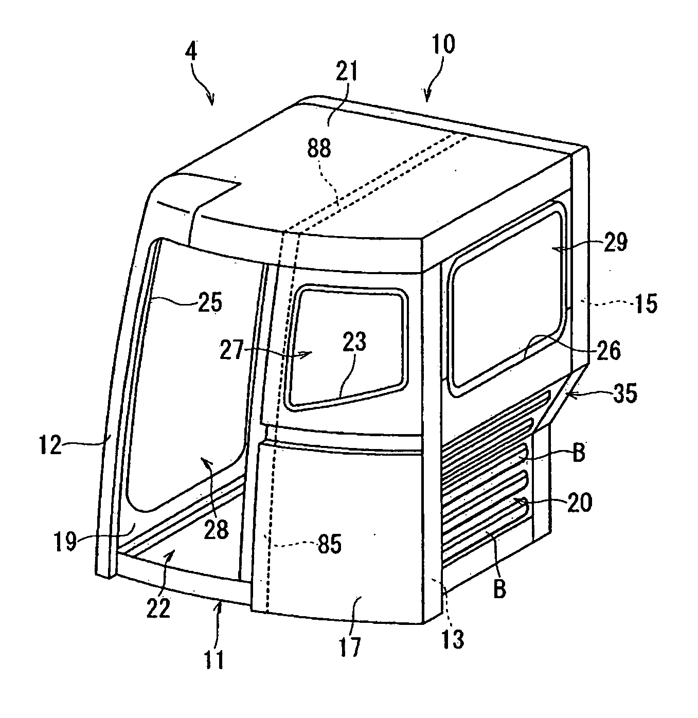
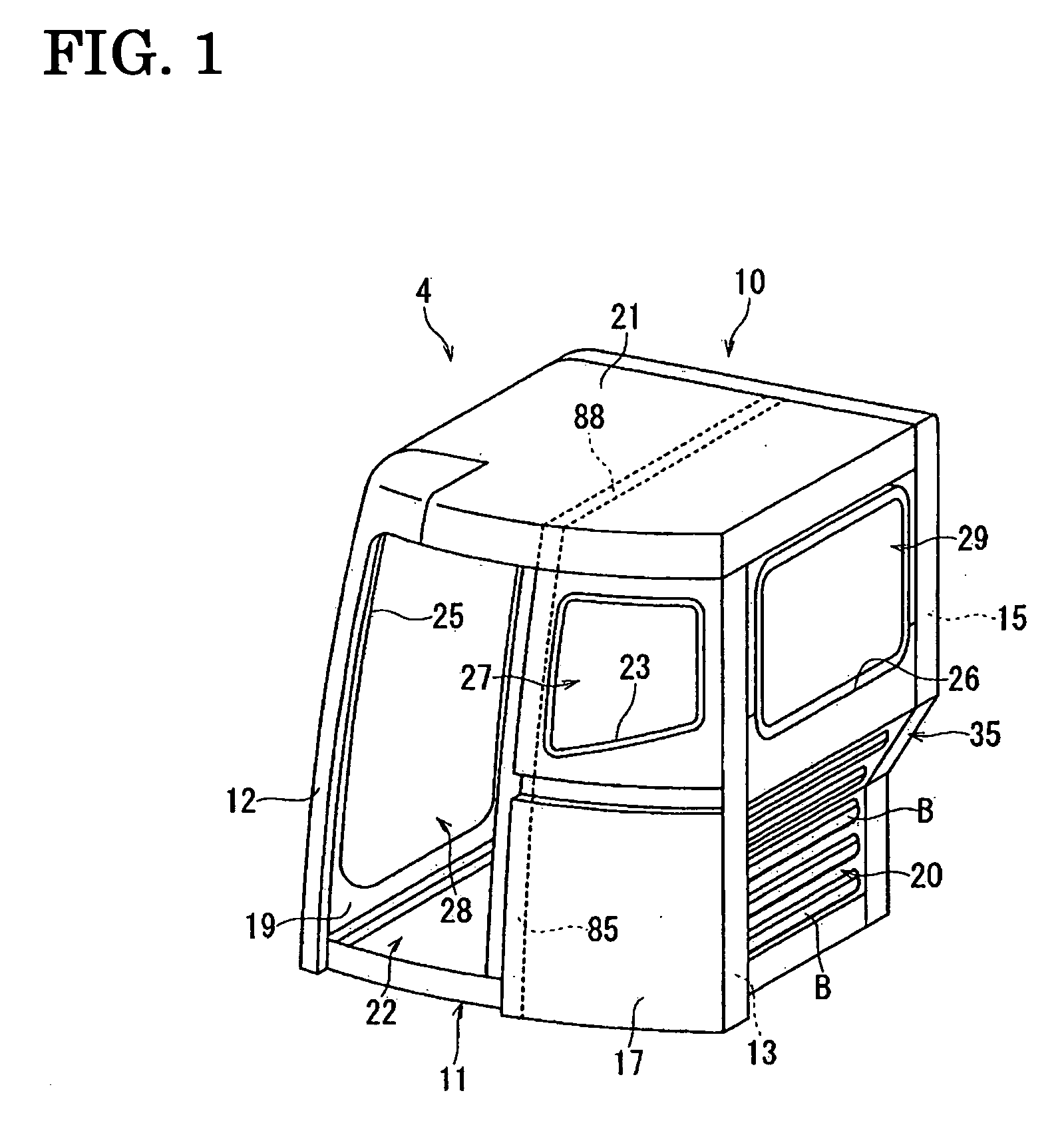
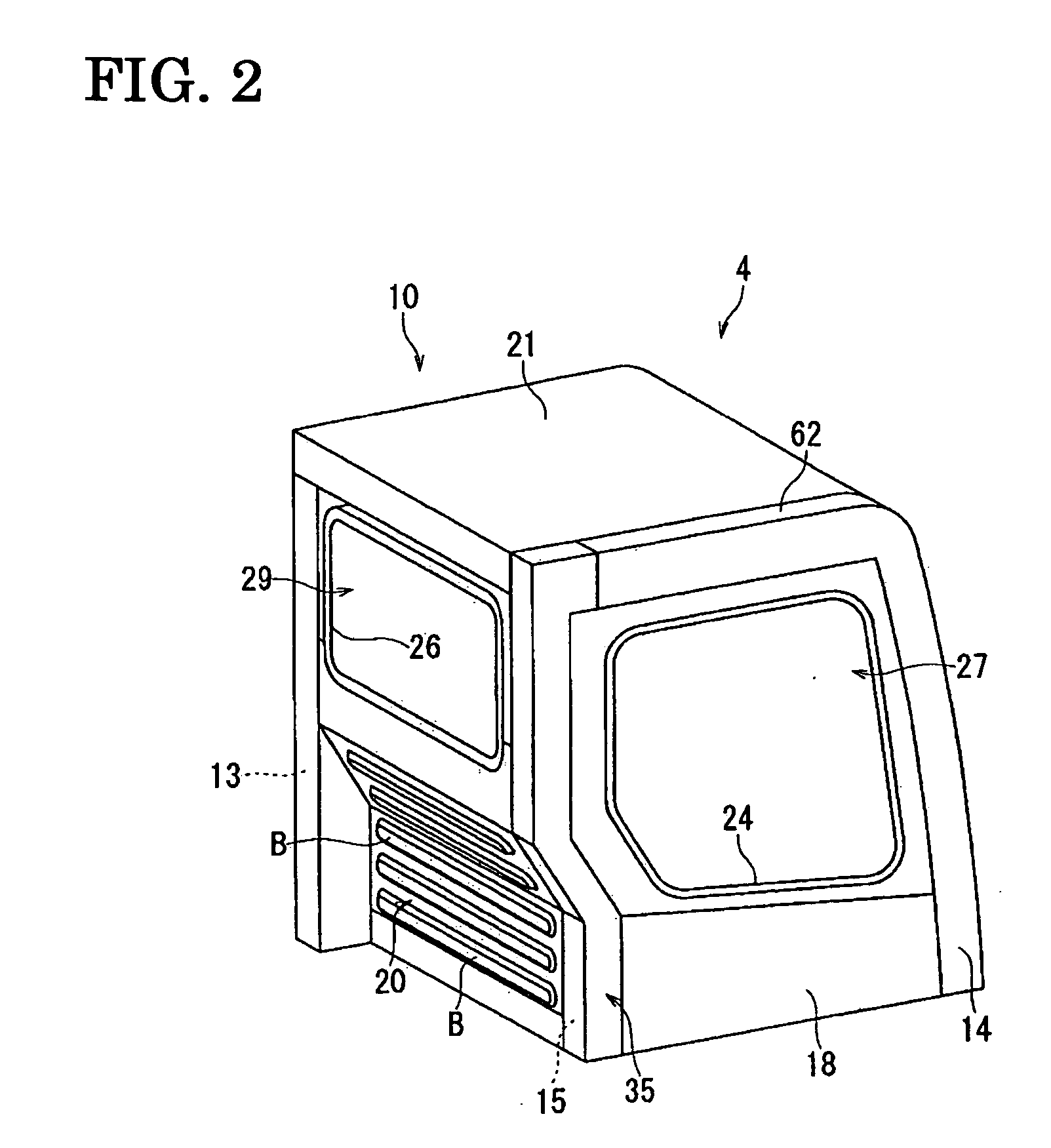
[0041] As shown in FIGS. 1 and 2, the cab 4 is composed of a cab body 10 and a floor frame 11 which close up the lower...


PUM


Abstract

A cab for a construction machine is provided which is cost effective, good in strength as a cab, usable in narrow sites where an obstacle exists, and good in front visibility and design. The cab for a construction machine has left front, left rear, right front and right rear pillars 12, 13, 14, 15 which vertically extend. The left rear and right rear pillars 13, 15 are made of a pipe material, and the rear part of the cab has greater rigidity than the front part of the cab. The left front and right front pillars 12, 14 are respectively constituted by at least two press-molded parts which are respectively formed into a specified shape by press molding.

Description

TECHNICAL FIELD [0001] The present invention relates to a cab for a construction machine such as hydraulic excavators. BACKGROUND ART [0002] Some cabs for a construction machine such as hydraulic excavators are composed of a framework made of pipe materials and panels etc. joined to the framework (see e.g., Patent Document 1). Other cabs are constructed by a plurality of panels joined to one another without use of a framework made of pipe materials (see e.g., Patent Document 2). More specifically, in the cabs having a framework formed from pipe materials, left front, left rear, right front and right rear posts each made of a pipe material are provided; the left front post and the right front post are coupled by upper and lower coupling members made of a pipe material; the left rear post and the right rear post are coupled by upper and lower coupling members made of a pipe material; the left front post and the left rear post are coupled by upper and lower coupling members made of a p...

Claims


Application Information

Patent Timeline
Patent Type & Authority Applications(United States)
IPC IPC(8): B60J7/00B62DB62D25/04B62D25/08B62D33/06E02F9/16
CPCE02F9/163B62D33/0617B62D25/08E02F9/16
Inventor MORI, TADASHITSUJI, KOUDOU
Owner KOMATSU LTD
Why Eureka
Try Eureka