Organic el display

a technology of organic el and el elements, applied in the direction of discharge tube luminescnet screens, discharge tube/lamp details, coatings, etc., can solve the problems of monotonically increasing or monotonically decreasing the concentration of dopant materials, and the degree of luminous efficiency of most organic el elements is low

Active Publication Date: 2007-02-01
JAPAN DISPLAY CENTRAL CO LTD
View PDF15 Cites 29 Cited by
  • Summary
  • Abstract
  • Description
  • Claims
  • Application Information

AI Technical Summary

Benefits of technology

[0019]FIG. 10 is a graph showing an example of a relation between a number of times each of the first and second operations is carried out and luminous efficiency of an organic EL element.

Problems solved by technology

However, under normal circumstances, the concentration of the dopant material monotonically increases or monotonically decreases along the thickness of the emitting layer.
For this reason, most of organic EL elements are low in the degree of luminous efficiency.

Method used


Image

  • Organic el display
  • Organic el display
  • Organic el display

Examples


Embodiment Construction

[0020] An embodiment of the present invention will be described below in detail with reference to the drawings. In the drawings, components having the same or similar function are denoted by the same reference symbol and duplicate descriptions will be omitted.

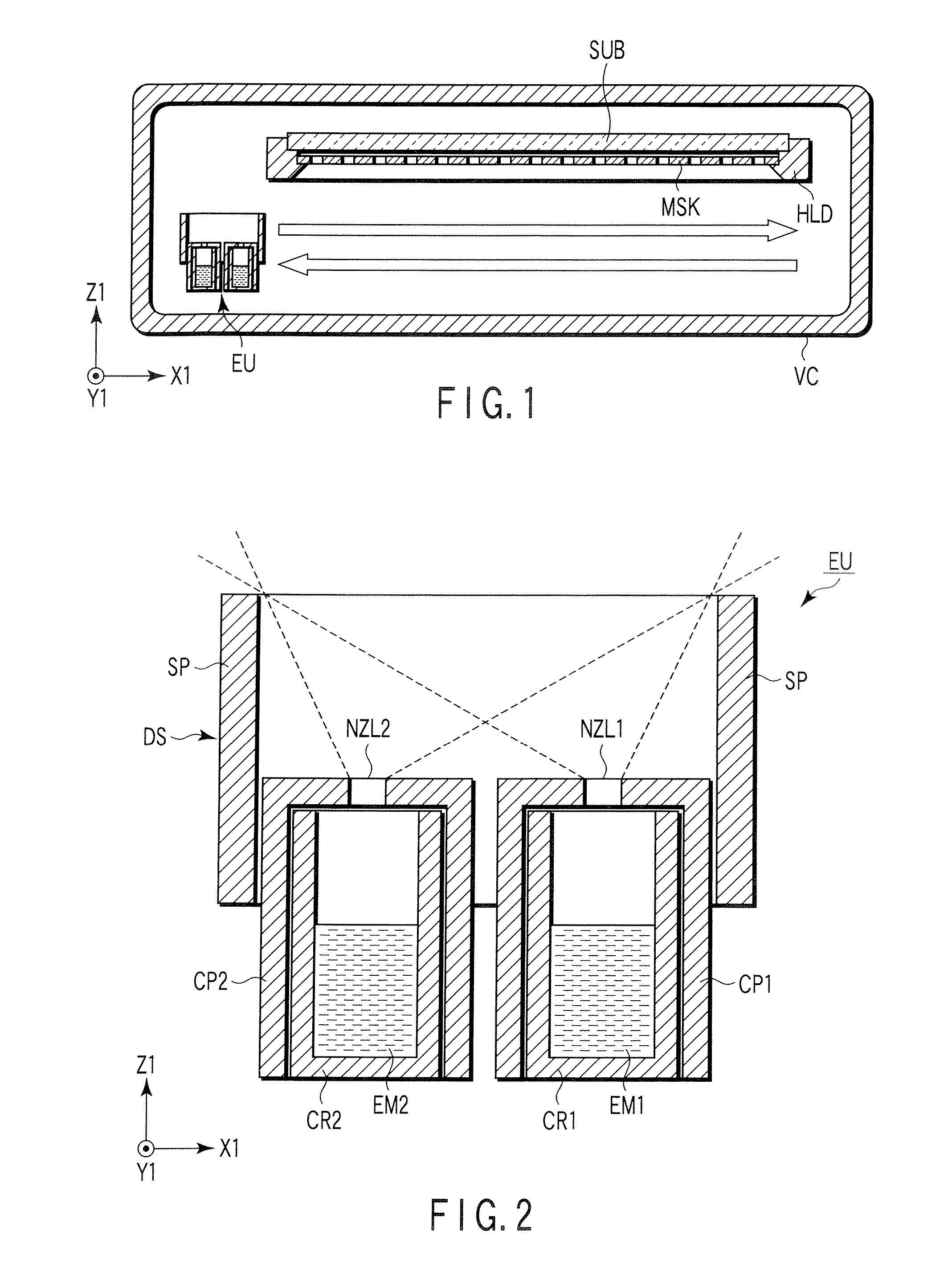
[0021]FIG. 1 is a sectional view schematically showing a vacuum evaporator that can be used in the process according to an embodiment of the present invention. FIG. 2 is a sectional view schematically showing the evaporation unit included in the vacuum evaporator shown in FIG. 1.

[0022] The vacuum evaporator shown in FIG. 1 includes a vacuum chamber VC to which an evacuation system is connected. Typically, the vacuum chamber VC is incorporated in a single-substrate processing apparatus including a multi-chamber system.

[0023] In the vacuum chamber VC, a substrate holder HLD, an evaporation unit EU, and a thickness sensor (not shown) are placed.

[0024] The substrate holder HLD detachably holds a substrate AS such that a film-fo...


PUM


Abstract

An organic EL element includes a pair of electrodes and an emitting layer interposed therebetween. The emitting layer is made of a mixture containing a host material and a dopant material. In the emitting layer, a concentration profile of the dopant material along a thickness direction includes at least two relative maximums or at least two relative minimums.

Description

CROSS-REFERENCE TO RELATED APPLICATIONS [0001] This application is based upon and claims the benefit of priority from prior Japanese Patent Application No. 2005-221591, filed Jul. 29, 2005, the entire contents of which are incorporated herein by reference.BACKGROUND OF THE INVENTION [0002] 1. Field of the Invention [0003] The present invention relates to an organic electroluminescent (hereinafter referred to as EL) element, an organic EL display, and a method of manufacturing an organic EL display. [0004] 2. Description of the Related Art [0005] An organic EL element has a structure in which an organic layer including an emitting layer is interposed between a pair of electrodes. The emitting layer normally made of a mixture containing a host material and a dopant material. The emitting layer can be formed by vacuum evaporation as described in JP-A 2003-157973 (KOKAI), for example. [0006] In view of increasing the degree of luminous efficiency, it is ideal to set the concentration of...

Claims


Application Information

Patent Timeline
Patent Type & Authority Applications(United States)
IPC IPC(8): H01L51/52H01L51/56
CPCH01L27/3244H01L51/56H01L51/5012H10K59/12H10K50/11H10K71/00
Inventor KITAMURA, KAZUKIISHIDA, TETSUOTAMEKAWA, MITSUGU
Owner JAPAN DISPLAY CENTRAL CO LTD
Why Eureka
Try Eureka