Method of voltage measurement and apparatus for same

a voltage measurement and voltage technology, applied in the direction of moving iron instruments, instruments, transportation and packaging, etc., can solve the problems of reduced measurement accuracy and high cost of apparatus, and achieve the effect of low cost and high accuracy

Inactive Publication Date: 2007-02-01
YAZAKI CORP
View PDF3 Cites 20 Cited by
  • Summary
  • Abstract
  • Description
  • Claims
  • Application Information

AI Technical Summary

Benefits of technology

[0009] The present invention is to provide a method of voltage measurement wit...

Problems solved by technology

However, in the conventional apparatuses, the devices following to the capacitor have variations in quality, temperature characteristic, and degradation thereof so that the...

Method used


Image

  • Method of voltage measurement and apparatus for same
  • Method of voltage measurement and apparatus for same
  • Method of voltage measurement and apparatus for same

Examples


first embodiment

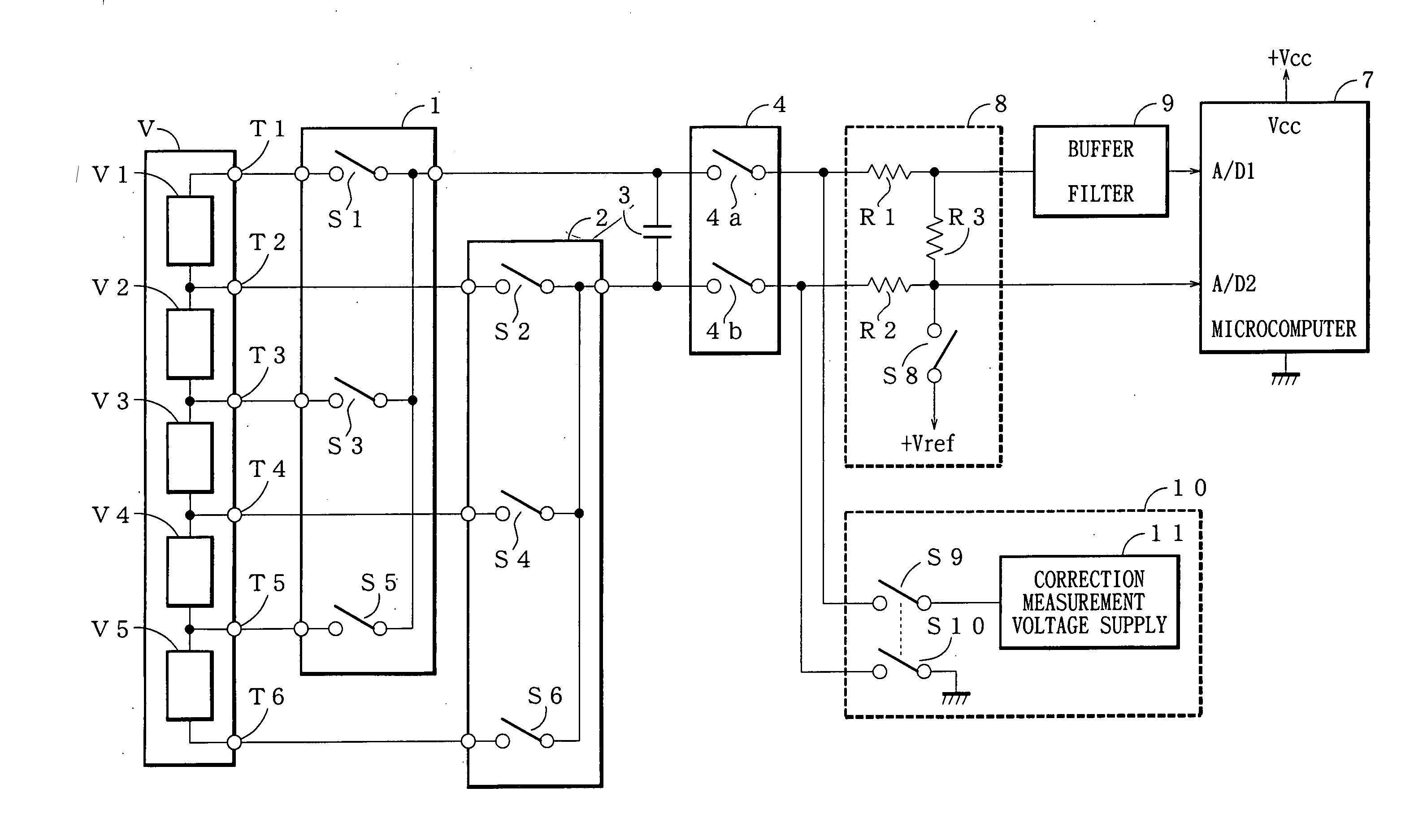
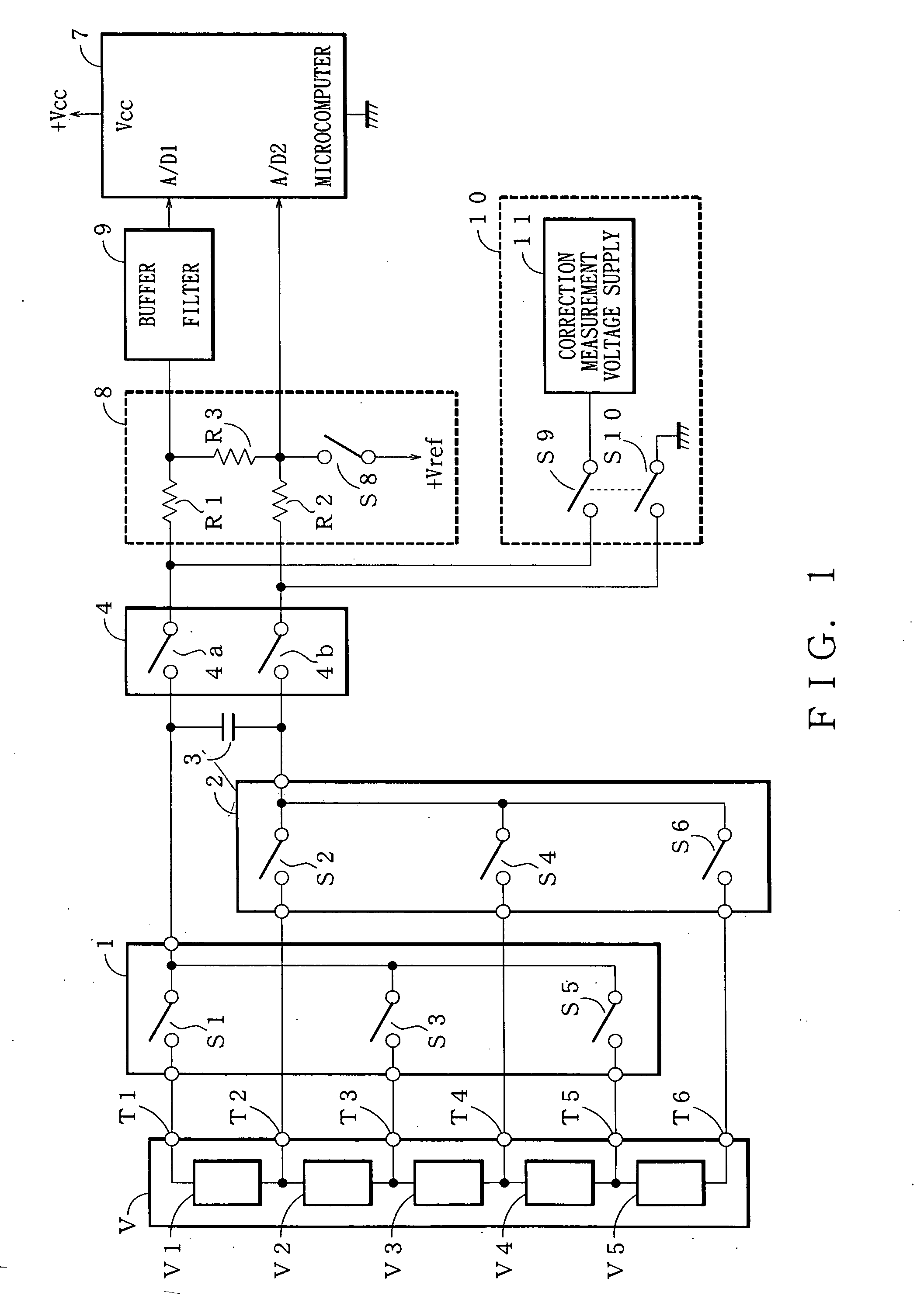
[0027]FIG. 1 shows a circuit of an apparatus for voltage measurement of the present invention. The apparatus for voltage measurement is a flying capacitor method. The apparatus for voltage measurement includes a first multiplexer 1 and second multiplexer 2 connected to voltage sensing terminals T1-T6 of a high voltage power supply V, a bipolar capacitor 3, a sample switch 4, a microcomputer 7, a reference voltage supply circuit 8, a buffer filter 9, and a correction measurement circuit 10. The high voltage power supply V, the first and second multiplexers 1, 2, and the capacitor 3 forms a charging unit. The reference voltage supply circuit 8, the buffer filter 9 and the microcomputer 7 forms a measuring unit.

[0028] The high voltage power supply V has 5 voltage supplies of V1-V5 (N=5, N is a number of batteries connected in series in the high voltage power supply of the present embodiment). Each voltage supply of V1-V5 is connected to respective voltage sensing terminals of T1-T6 (N+...

second embodiment

[0051]FIG. 4 shows a circuit of an apparatus of measuring a voltage of the present invention.

[0052] The apparatus of FIG. 4 shows almost the same configuration as FIG. 1 except a reference voltage supply circuit 8 and a correction measurement circuit 10. As shown in FIG. 4, the reference voltage supply circuit 8 has resistors R1-R3, a first switch 8a and a second switch 8b. The first switch 8a is connected between a junction of the resistors R2, R3 and a reference voltage supply +Vref, which provides a high voltage or the highest voltage of a measurement full scale of a microcomputer 7. The second switch 8b is connected between the junction of the resistors R2, R3 and the ground, which provides a low voltage or the lowest voltage of the measurement full scale of the microcomputer 7.

[0053] The voltage of the reference voltage supply +Vref is set to equal +Vcc of a drive voltage of the microcomputer 7 or at most the drive voltage +AVcc (≦+Vcc).

[0054] A correction measurement circuit...

third embodiment

[0070]FIG. 6 shows a circuit of an apparatus for voltage measurement of the present invention.

[0071] The apparatus for voltage measurement of FIG. 6 has the almost same configuration as that of FIG. 4 except a formation of a reference voltage circuit 8. The reference voltage supply +Vref functions also as a correction measurement voltage supply similarly to FIG. 4. In the reference voltage supply circuit 8 of FIG. 6, the first switch 8a of FIG. 4 is replaced with a resistor R4.

[0072] In the following, a process of measuring a voltage with flying capacitor method is explained. All switches S1-S6 of a first and second multiplexers 1 and 2, 4a and 4b of a sample switch 4, and a first switch 8b of the reference voltage supply circuit 8 are opened. The switches S1 and S2 of the first and second multiplexers 1 and 2, respectively are closed. A voltage supply V1, voltage sensing terminal T1, switch S1, capacitor 3, switch S2 and voltage sensing terminal T2 form a closed circuit. The volta...


PUM


Abstract

The present invention is to provide a method of voltage measurement and an apparatus for the same having an improved accuracy and low cost. The apparatus for voltage measurement of a voltage supply includes: a charging unit for charging a capacitor for a prescribed period of time of charging; a measuring unit for measuring a charge of the capacitor charged during a prescribed period of time of charge measurement; and a microcomputer for calculating a voltage of the voltage supply from a measurement value of the charge, the microcomputer including: a correction value calculating program for applying a voltage of a correction measurement voltage supply to the measuring unit, measuring the voltage of the correction measurement voltage supply during the prescribed period of time of charging, and calculating a correction value from a difference between a measurement value and a theoretical value of the voltage of the correction measurement voltage supply, and a voltage measurement program for subtracting the correction value calculated at the correction value calculating program from the measurement value of the charge during the prescribed period of time of charge measurement and for calculating the voltage of the voltage supply.

Description

BACKGROUND OF THE INVENTION [0001] 1. Field of the Invention [0002] The present invention relates to a method of voltage measurement and an apparatus for the same and especially to a method and apparatus of voltage measurement of each voltage supply of a plurality of voltage supplies connected in series. [0003] 2. Description of the Related Art [0004] An electric motor vehicle has a high voltage supply which is formed with a plurality of batteries (voltage supplies) connected in series. JP,H11-248755,A discloses a flying capacitor method for measuring voltage of each voltage supply of a plurality of batteries. [0005] Each voltage supply is connected to a capacitor with a switch and disconnected each other with a multiplexer to measure a charge in the capacitor and to determine the voltage of the voltage supply. [0006] A measurement is achieved by charging the capacitor with every each voltage supply and measuring the charge of the capacitor as shown in FIG. 8. The measurement of the...

Claims


Application Information

Patent Timeline
IPC IPC(8): G01R5/14
CPCG01R19/2503G01R31/3658G01R31/3648G01R31/362G01R31/3835G01R31/396
Inventor KAWAMURA, YOSHIHIRO
Owner YAZAKI CORP
Why Eureka
Try Eureka