
Filters and antennas for microwaves and millimetre waves, based on open-loop resonators and planar transmission lines

a filter and micro-wave technology, applied in waveguides, antenna feed intermediates, filters, etc., can solve the problems of not being compatible with circuit manufacturing technologies (printed circuits, microelectronic technologies), and the practice of using the above structures as filters, antennas, etc., and achieve good directivity and polarisation.

Inactive Publication Date: 2007-02-01
AUTONOMOUS UNIVERSITY OF BARCELONA
View PDF3 Cites 45 Cited by
  • Summary
  • Abstract
  • Description
  • Claims
  • Application Information

AI Technical Summary

Benefits of technology

[0011] Moreover, said filters present low insertion losses in the pass band, their design is very simple and their manufacturing process is compatible with printed- and integrated-circuit manufacturing technologies.
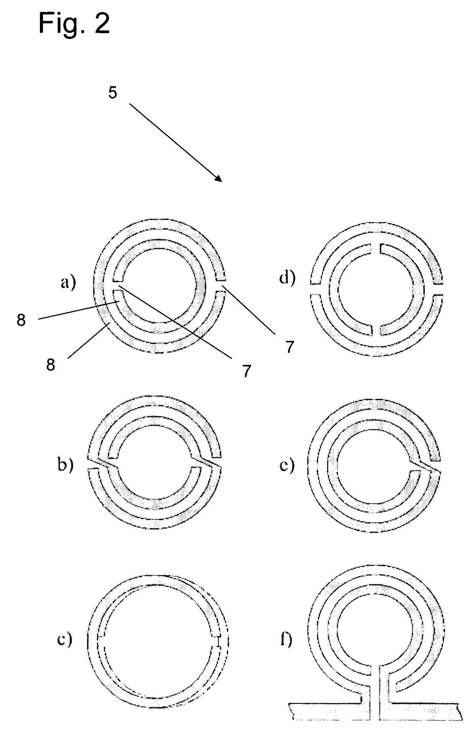
[0025] The combination of all these characteristics of the open rings allows a resonant structure to be achieved over a wide frequency margin.
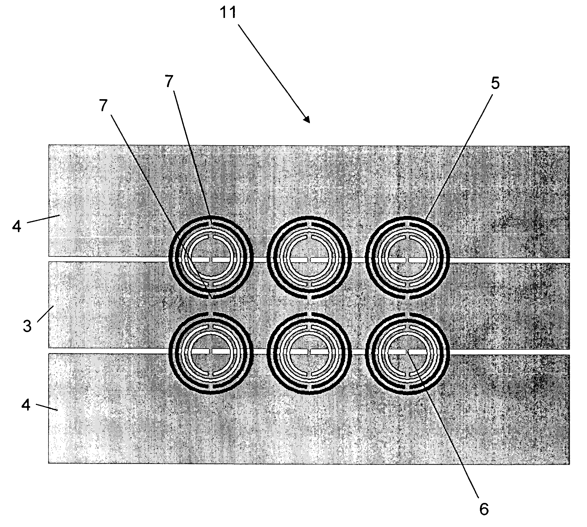
[0029] The fact that the radiation diagrams show good levels of directivity and polarisation means that the filter can behave as an antenna, since it eliminates the incident waves by radiating them. Variants can also be implemented based on groupings of batteries of antennas. Suitable adjustment of the ring properties allows emphasis of the radiation properties of said structures, permitting their use for the emission and reception of electromagnetic waves.

Problems solved by technology

One limitation on the practical utilisation of the above structures as filters, antennas, etc., lies in the fact that they are not compatible with circuit manufacturing technologies (printed circuits or microelectronic technologies), since they are three-dimensional structures.
Another major limitation on the aforesaid structures relates to the fact that they present highly significant pass-band losses, making them unviable for use as filters and antennas.
Such losses are due not so much to radiation or to ohmic or dielectric losses, but are rather the consequence of lack of adaptation between the medium and the measuring probes.

Method used


Image

  • Filters and antennas for microwaves and millimetre waves, based on open-loop resonators and planar transmission lines
  • Filters and antennas for microwaves and millimetre waves, based on open-loop resonators and planar transmission lines
  • Filters and antennas for microwaves and millimetre waves, based on open-loop resonators and planar transmission lines

Examples


Embodiment Construction

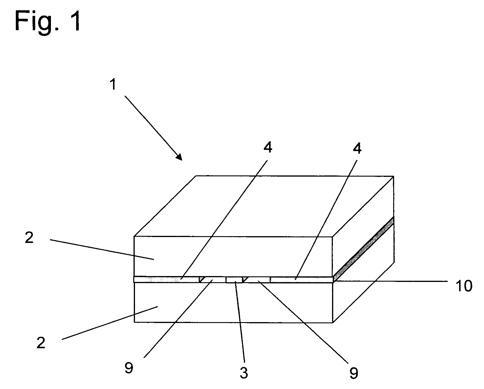
[0035]FIG. 1 of this invention shows a planar transmission medium 1 structure of the buried coplanar wave guide type, i.e., with dielectric substrate 2 on both sides of the central metallic plane 10 on which the conductor strip 3 is formed, separated from the metallic ground planes 4 by the slots 9. Alternatively, the coplanar wave guide can consist of the same structure as that shown in FIG. 1, though with dielectric substrate 2 only on one of the sides of the central metallic plane 10, which contains the central conductor and the metallic ground planes 4. Or any other type of configuration with multiple layers of dielectric substrate 2. Other media of propagation are also possible, such as microstrip lines, striplines, and in general any planar transmission medium.

[0036] For the embodiment of high-performance filters and antennas it is advisable to use dielectric substrates 2 with low dielectric losses in order to obtain frequency responses with the lowest possible losses in the ...


PUM


Abstract

Filter for microwaves and millimetER waves, characterised in that it comprises a planar transmission medium (1) that it includes a conductor strip (3), metallic ground plane (4) and dielectric substrate (2) and in that it includes at least one split rings resonator (5a, 5b, 5c, 5d, 5e and 5f)

Description

TECHNICAL FIELD OF THE INVENTION [0001] This invention relates to microwave and millimeter-wave filters and antennas based on split rings resonators and planar transmission lines. BACKGROUND OF THE INVENTION [0002] Known in the art are periodic structures based on split rings resonators for the synthesis of band-rejection frequency responses and for achieving focalisation of electromagnetic waves propagating in space. Said structures are based on the fact that in the neighbourhood of the resonance frequency such rings can behave as an effective medium with extreme permeability values (positive beneath the resonance and negative above it). To achieve this said structures have to be irradiated with the magnetic field polarised parallel to the axis of the rings. This arrangement inhibits the propagation of electromagnetic signals in a narrow frequency band around the resonance frequency, thereby achieving a band-rejection response. [0003] Also known are periodic structures based on spl...

Claims


Application Information

Patent Timeline
Patent Type & Authority Applications(United States)
IPC IPC(8): H01P1/203H01P1/201H01Q7/00H01Q9/26
CPCH01P1/2013H01Q9/265H01Q7/00
Inventor MARTIN ANTOLIN, JUAN FERNANDOBONACHE ALBACETE, JORGEMARQUES SILLERO, RICARDOBAENA DOELLO, JUAN DOMINGOMARTEL VILLAGRAN, JESUSMEDINA MENA, FRANCISCOFALCONE LANAS, FRANCISCOLOPETEGUI BEREGANA, JOSE MARIABERUETE DIAZ, MIGUELSOROLLA AYZA, MARIO
Owner AUTONOMOUS UNIVERSITY OF BARCELONA
Learn More