Method and system for evaluating moving image quality of displays

a technology of moving image and display, applied in the field of moving image quality evaluation, can solve the problems of difficulty in specifying pixels that correspond to the start and end of blurring, and achieve the effect of accurately evaluating the moving image quality of the screen

Inactive Publication Date: 2007-02-01
OTSUKA DENSHI CO LTD
View PDF10 Cites 17 Cited by
  • Summary
  • Abstract
  • Description
  • Claims
  • Application Information

AI Technical Summary

Benefits of technology

[0017] As described so far, according to the present invention, by capturing an image of a still test pattern while moving the field of view of the image sensor at the same velocity at which the field of view of the image sensor pursues the move of the scrolled test pattern and then measuring a second blurred edge, ...

Problems solved by technology

This is because there are cases where it is difficult to sp...

Method used


Image

  • Method and system for evaluating moving image quality of displays
  • Method and system for evaluating moving image quality of displays
  • Method and system for evaluating moving image quality of displays

Examples


Embodiment Construction

[0024] Specific embodiments of the present invention will be hereinafter described in detail referring to the appended drawings.

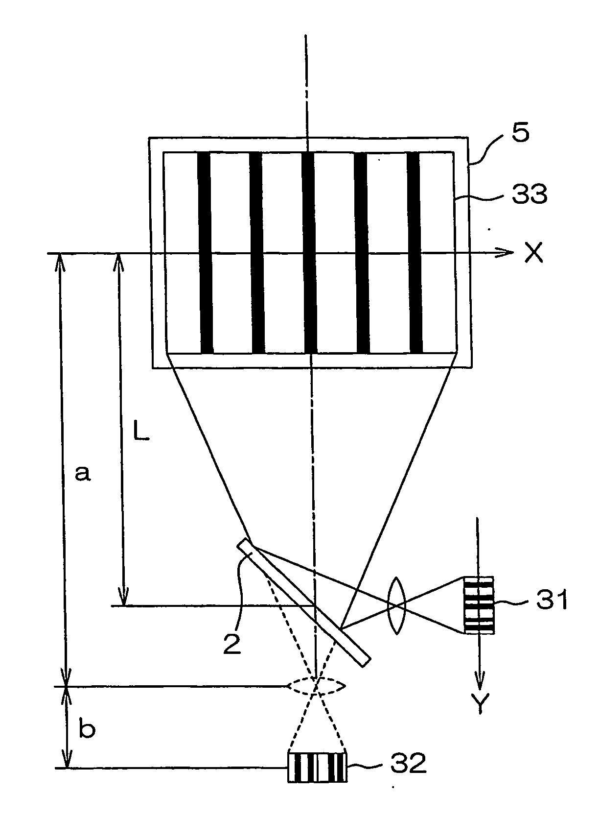
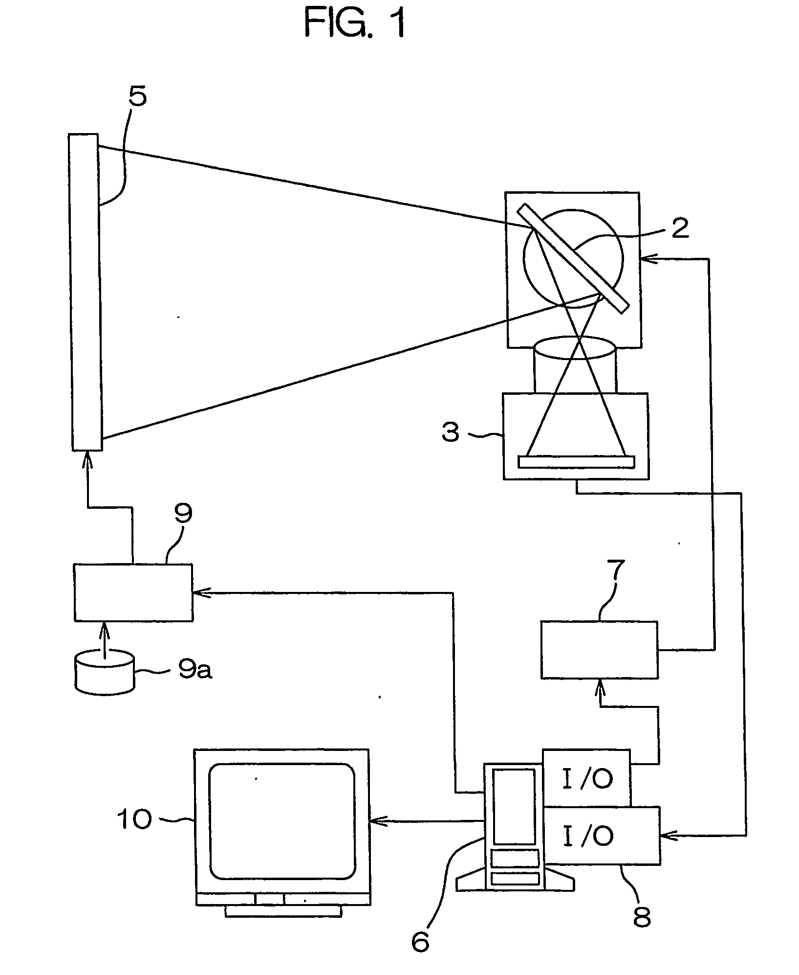
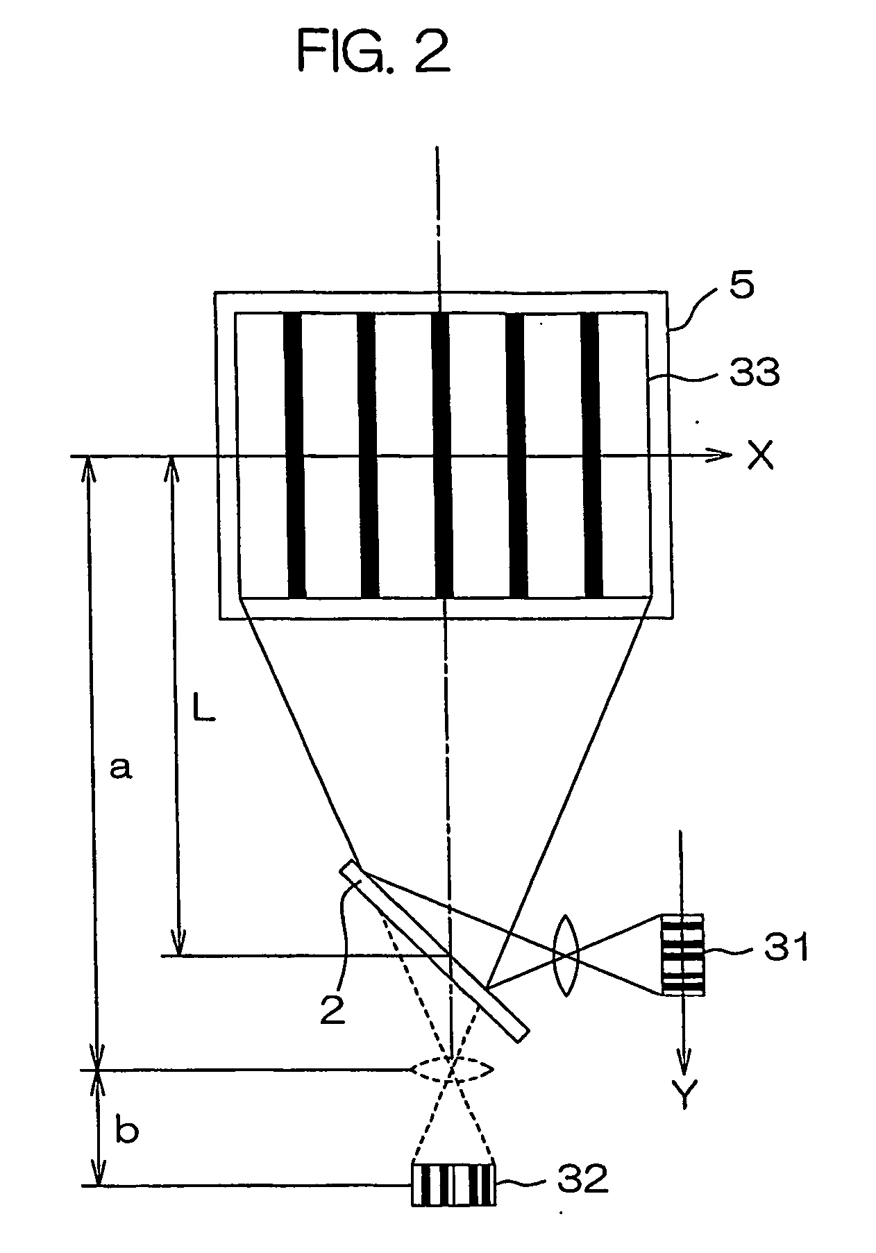
[0025]FIG. 1 is a block diagram illustrating the configuration of a system for evaluating moving image quality of displays according to the present invention. The system for evaluating moving image quality of displays includes a galvanometer mirror 2, and a CCD camera 3 that captures images of a screen 5 of a display device subject to evaluation through the galvanometer mirror 2.

[0026] The galvanometer mirror 2 comprises a mirror attached to the rotation axis of a permanent magnet that is rotatably disposed in a magnetic field generated when electric current flows through a coil, which allows the mirror to rotate smoothly and rapidly.

[0027] The CCD camera 3 has a field of view for imaging that covers a part of or the entire screen 5 of the display device subject to evaluation. The galvanometer mirror 2 is disposed between the CCD camera 3 and the screen ...


PUM


Abstract

A test pattern is moved on a screen 5 subject to measurement with the field of view of an image sensor pursuing the motion of the test pattern so as to observe BEW. Subsequently, the field of view 33 of the image sensor is moved at the same velocity vc as in the foregoing observation to capture an image of a static pattern PE, and a blur width W along the scrolling direction that appears in a distribution profile of the captured image is observed. Based upon the blur width W and the exposure time of the image sensor for capturing the image of the static pattern PE, the moving velocity of the test pattern at the time of observation of the BEW is estimated, and by using the moving velocity, the BEW is normalized. Evaluation of the moving image quality of the screen is carried out by using the normalized N BEW. The moving velocity of the original test pattern can thus be estimated easily and accurately, and accordingly, the moving image quality of the screen can be evaluated accurately.

Description

TECHNICAL FIELD [0001] The present invention relates to a method and system for evaluating moving image quality of displays which is capable of evaluating moving image quality of displays based on blurring of a scrolled test pattern displayed on a screen of a display device subject to evaluate. PRIOR ART [0002] Evaluation of moving image quality is conducted by measuring blurred edge of a moving image displayed on a screen of a display device such as a Liquid Crystal Display (LCD), Cathode Ray Tube (CRT) display, Plasma Display Panel (PDP), or Electroluminescence (EL) display. One method of such evaluation is a process in which a camera is adapted to pursue the move of a scrolled image similar as a rotation of eye ball while pursuing by human eye, and capture an image thereof as a stationary image, and the sharpness of the captured stationary image is evaluated. In the case of a display device with an image hold type display with a long liquid crystal response time such as LCD, in p...

Claims


Application Information

Patent Timeline
IPC IPC(8): G06T15/70G06T1/00H04N17/04G09G3/00G09G5/34
CPCG09G5/34G09G3/006
Inventor OKA, KOICHIENAMI, YOSHI
Owner OTSUKA DENSHI CO LTD
Why Eureka
Try Eureka