Optical encoder having slanted optical detector elements for harmonic suppression

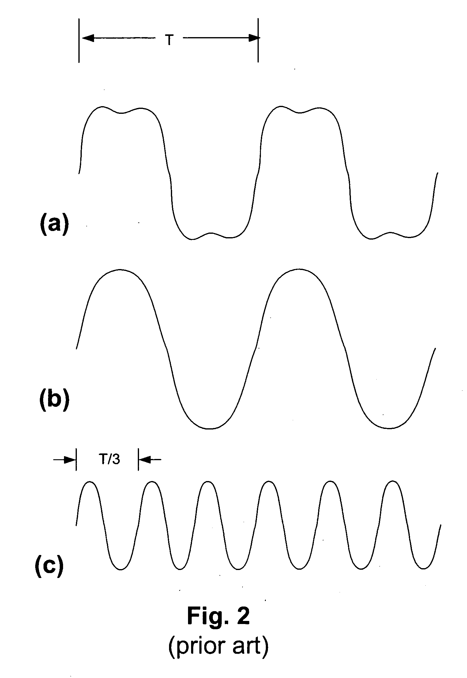
a detector element and optical encoder technology, applied in the field of optical position encoders, can solve the problems of incongruity in the width of the detector element t/3, unsuitable for all applications, and discourage the use of the detector element, so as to improve the alignment tolerance, improve the operation effect, and improve the tolerance of contamination

Inactive Publication Date: 2007-02-01
THE GSI GRP LLC
View PDF16 Cites 4 Cited by
  • Summary
  • Abstract
  • Description
  • Claims
  • Application Information

AI Technical Summary

Benefits of technology

[0014] Among the other benefits achieved by the disclosed optical encoder are improved alignment tolerance and greater tolerance of contamination during operation. These benefits arise in part from a “zig-zag” or repeated “chevron” shape of the optical detectors that extends over multiple cycles. The pattern provides for effective harmonic filtering over a relatively large range of rotational misalignment about the detector axis. Also, because of the natural redundancy of the repeated shape, the detectors can operate effectively even in the presence of small amounts of contamination that may block some segments.

Problems solved by technology

While encoders employing harmonic suppressing photodetector arrays such as shown in the Thorburn et al. published application can achieve good suppression of undesired harmonic components, they may not be suitable for all applications.
However, the need for detector elements having a width of T / 3 is to some extent inconsistent with a four-bin sampling approach.
While these layouts serve to accommodate the use of relatively wide detector elements in the context of four-bin sampling, they may have other drawbacks that might discourage their use in any particular encoder.

Method used


Image

  • Optical encoder having slanted optical detector elements for harmonic suppression
  • Optical encoder having slanted optical detector elements for harmonic suppression
  • Optical encoder having slanted optical detector elements for harmonic suppression

Examples


Embodiment Construction

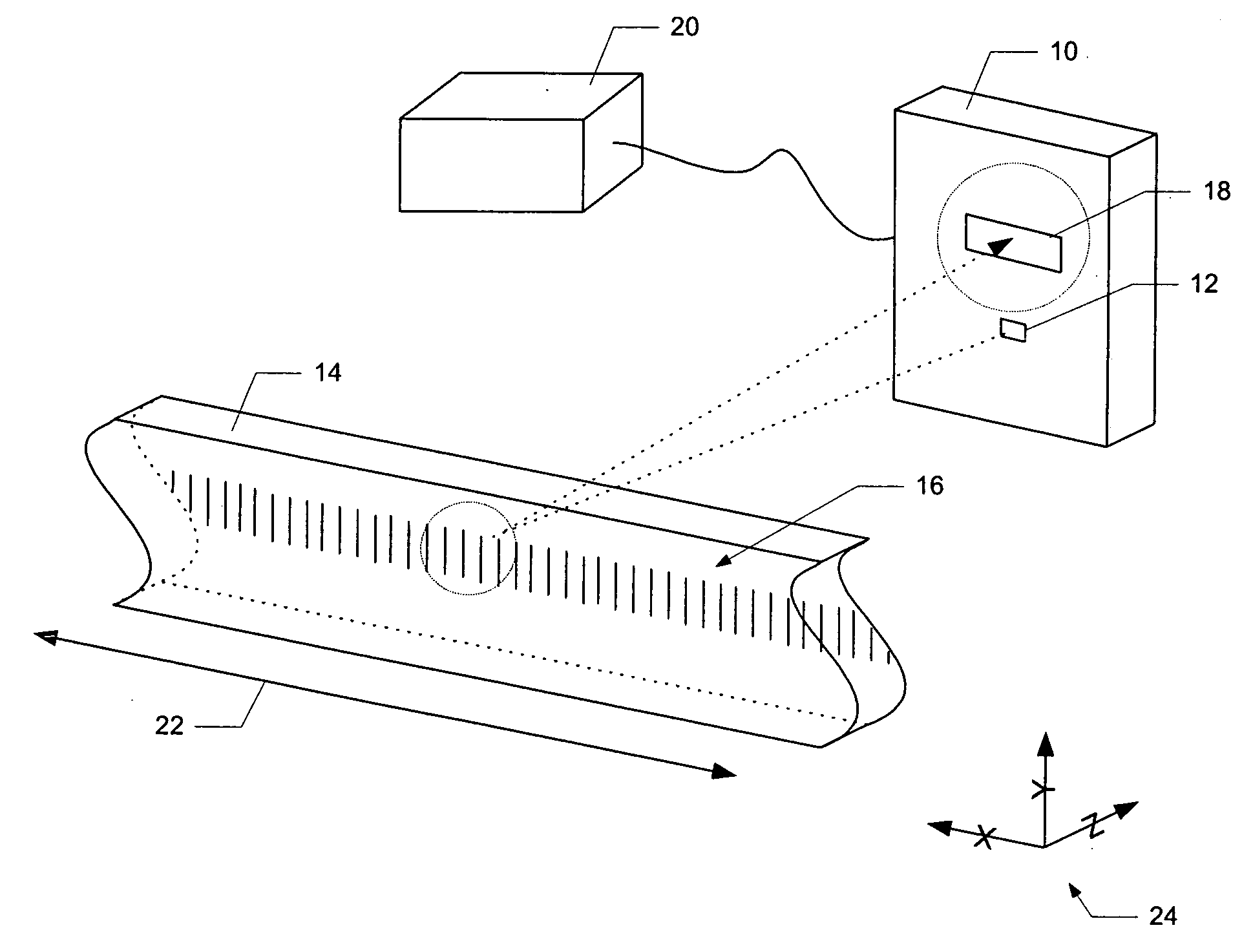
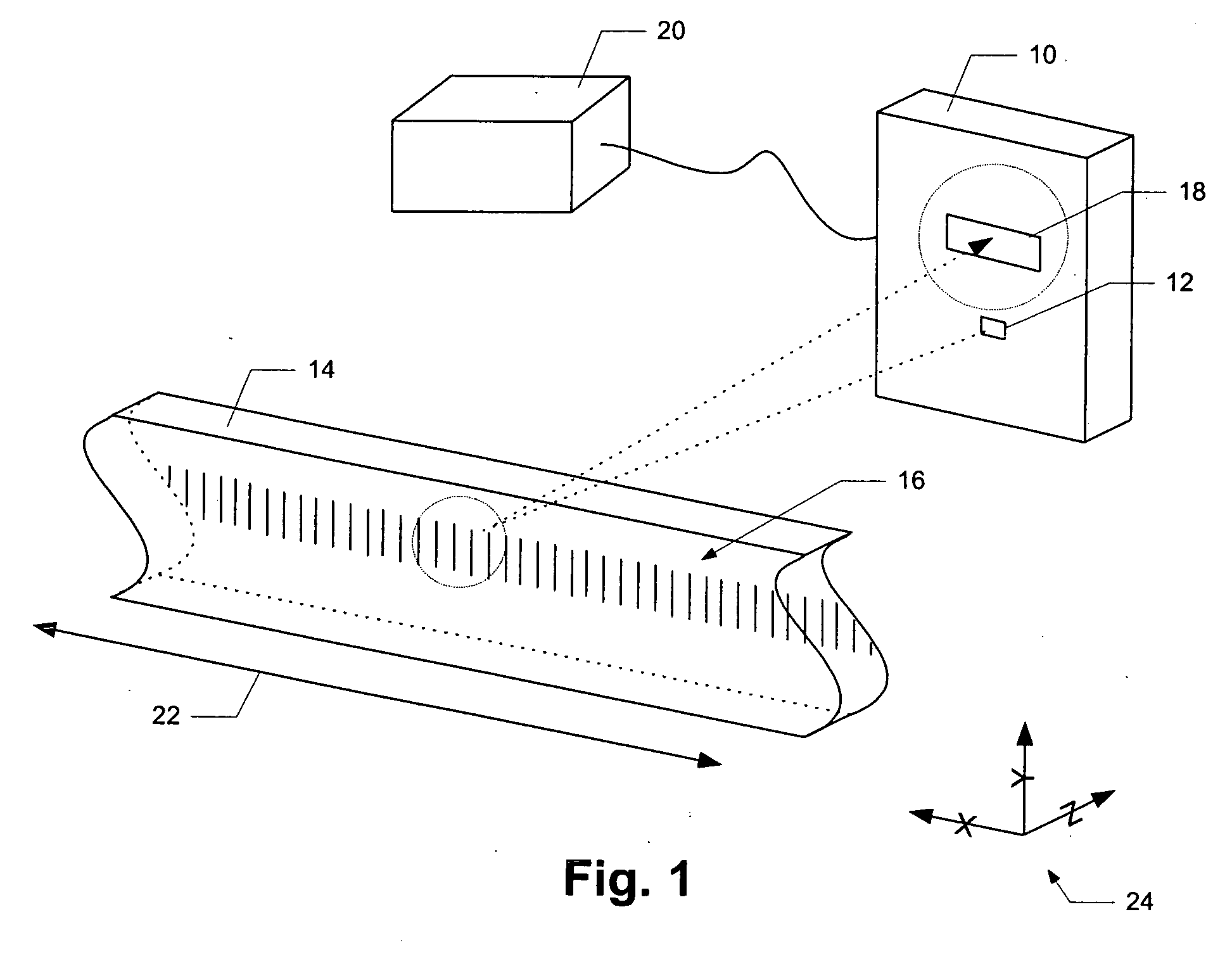
[0019] In FIG. 1, sensor apparatus 10 is installed as part of a reflective, diffractive optical encoder. A source 12 illuminates a scale 14 on which a periodic, reflective diffraction grating 16 has been created. Light from the source 12 is reflectively diffracted from the scale 14 toward the sensor apparatus 10, which in the illustrated embodiment includes an optical detector 18. The diffraction grating 16 generates multiple orders of diffracted light which interfere with each other to form an optical fringe pattern (not illustrated) on the detector 18. The samples from the detector 18 are sent to an electronic processor 20 which calculates a fringe phase for each sample.

[0020] The fringe pattern is ideally a sinusoid characterized by a period P. Conceptually, when the scale 14 moves laterally relative to the detector 18 along the direction indicated by line 22, the fringe pattern moves a proportional distance on the face of detector 18. An accurate measurement of the changes in t...


PUM


Abstract

An optical encoder includes a source of a light beam, an optical grating that generates a spatial pattern of interference fringes, and an optical detector which includes generally elongated detector elements that sample the interference fringe pattern at spatially separated locations along the direction of motion of the grating. Each detector element has one or more segments slanted along the direction of motion of the grating by an integer multiple of the period of an undesirable harmonic component of the fringe pattern, thereby spatially integrating the harmonic component and suppressing its contribution to an output of the detector. One specific detector type includes parallel elongated rectangular elements in a rectangular array that is rotated slightly about a Z axis; another type includes detector elements arranged to form a non-rectangular parallelogram. Another type of detector includes detector elements that each have multiple elongated rectangular segments which may be arranged into two non-parallel sets. The two sets can be further arranged in an alternating fashion so as to impart a zig-zag or chevron shape to each detector element.

Description

BACKGROUND OF THE INVENTION [0001] The present invention is related to the field of optical position encoders, and more particularly to optical position encoders employing techniques for suppressing undesirable harmonic components appearing in a periodic optical interference pattern within the encoder. [0002] One general type of optical position encoder employs a source of coherent light, a diffraction grating that is movable with respect to the source, and a detector that is used to sample a pattern of interference fringes created by light from the source that is diffracted by the diffraction grating. As the grating moves with the object whose position is being measured, the pattern of interference fringes has an apparent motion by a proportional amount. The detector samples the pattern at a sufficient number of locations to create an estimate of the spatial phase of the interference fringes, which is readily convertible into an estimate of the position of the object. [0003] In one...

Claims


Application Information

Patent Timeline
Patent Type & Authority Applications(United States)
IPC IPC(8): G01B11/02G01B9/02
CPCG01D5/38
Inventor MITCHELL, DONALD K.THORBURN, WILLIAM G.
Owner THE GSI GRP LLC
Why Eureka
Try Eureka