Batch mixer

a technology of mixing mixer and mixing plate, which is applied in the direction of rotary mixing mixer, mechanical equipment, transportation and packaging, etc., can solve the problems of large installation space, difficult pressure control, and complicated labor

Active Publication Date: 2007-02-01
KOBE STEEL LTD
View PDF32 Cites 17 Cited by
  • Summary
  • Abstract
  • Description
  • Claims
  • Application Information

AI Technical Summary

Benefits of technology

[0022] This makes possible to more sensitively adjust the moving

Problems solved by technology

However, since the batch mixer of U.S. Pat. No. 5,783,983 detects the position of the floating weight by an ON/OFF signal from the limit switch, the position of the floating weight must be changed in order to change the weight position, and its labor was complicated.
Further, in the above-described batch mixer, the pneumatic/hydraulic pressure converter must be installed around the batch mixer, and a large installing space was required.
Additionally, in the above-described batch mixer, it is theoretically possible to change the pressing pressure of the weight by changing air supply to the air pressure side of the pneumatic/hydraulic pressure converter, but a large volume of air supply/discharge is necessary if the control of changin

Method used


Image

  • Batch mixer
  • Batch mixer
  • Batch mixer

Examples


Embodiment Construction

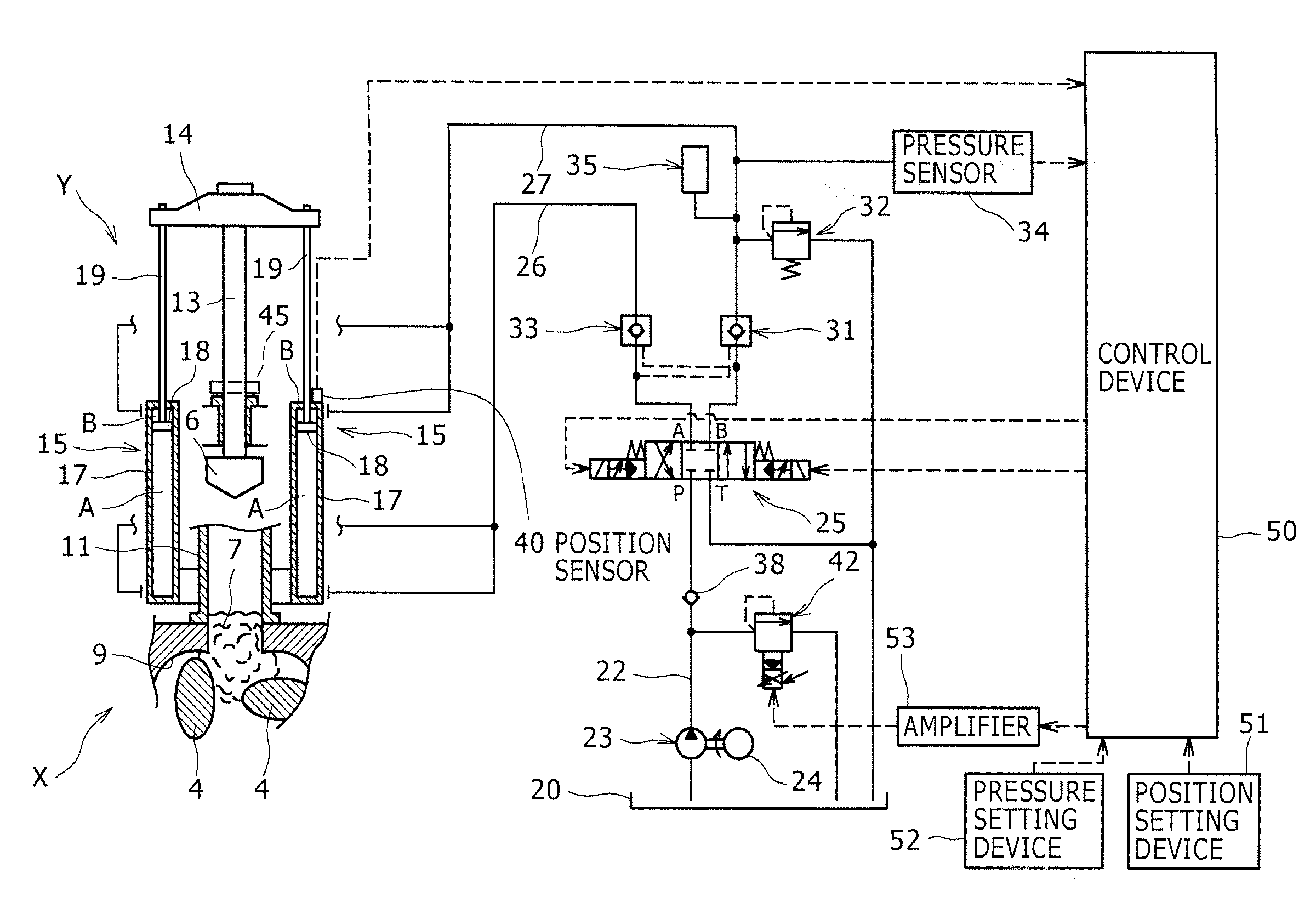
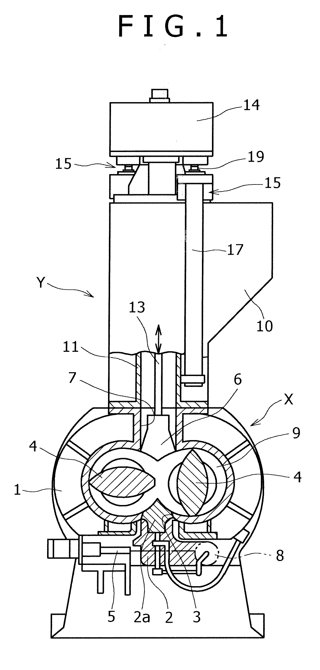
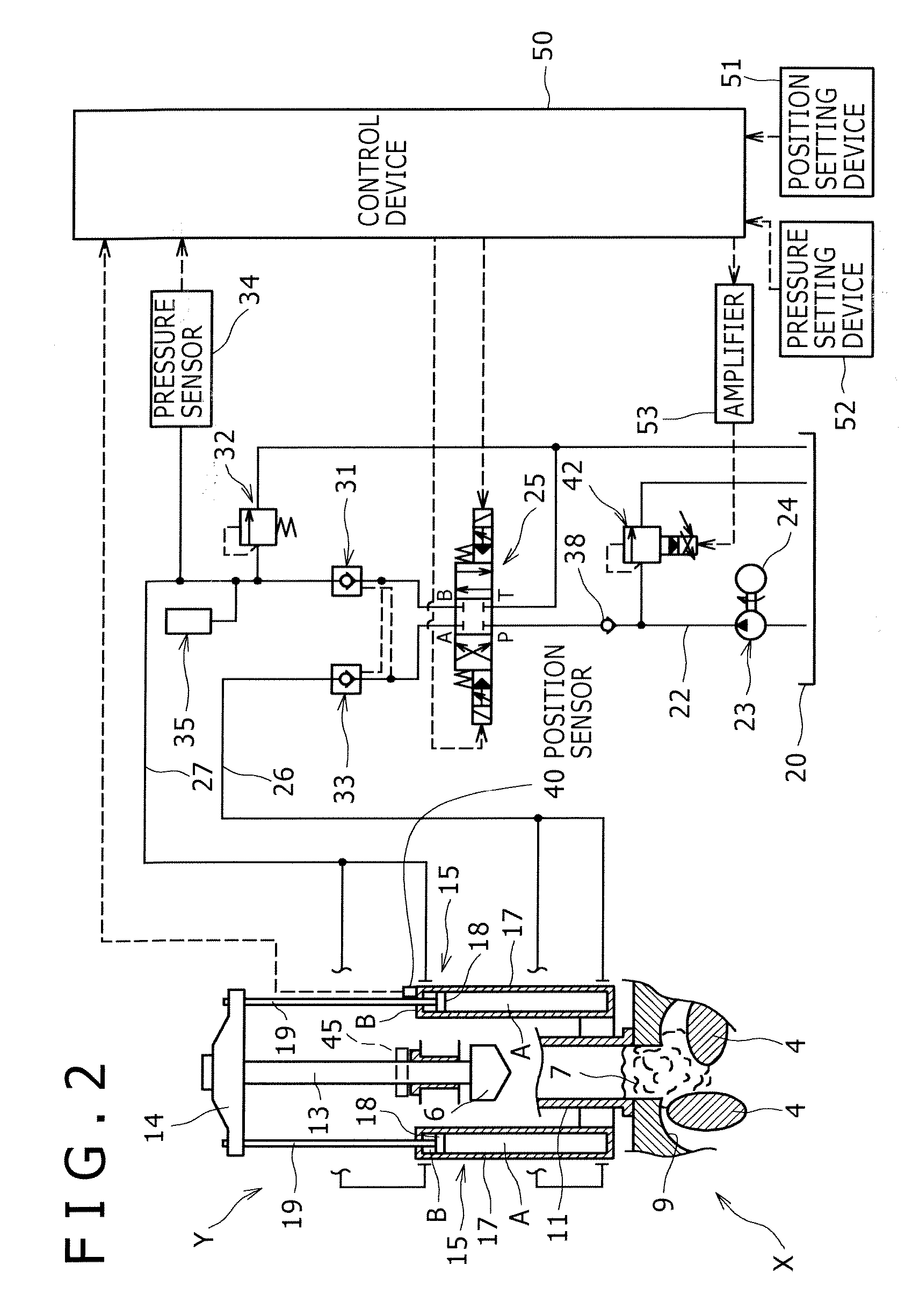
[0027] Next, description will be made for an example of the entire constitution of the batch mixer according to an embodiment of the present invention with reference to FIG. 1. FIG. 1 is the partial sectional view showing the entire constitution of the batch mixer.

[0028] A batch mixer X whose entire constitution is shown in FIG. 1 is an apparatus that mixes mixing materials such as rubber and resin, for example, and it includes a chamber 1 as a mixer main body having a mixing chamber 9 therein, mixing rotors 4 that mix the mixing materials in the mixing chamber 9, and a floating weight 6 for pressing the mixing materials into the mixing chamber 9 with a predetermined pressure, as primary constitutions.

[0029] In the chamber 1, the mixing chamber 9 having a cross-section of a shape, where two circular shapes are laid horizontally and partially connected to each other, is formed. A supply port 7 is formed on the upper portion of the central area in the transverse direction of the mix...


PUM

PropertyMeasurementUnit
Weightaaaaaaaaaa
Pressureaaaaaaaaaa

Abstract

A batch mixer, which includes a floating weight that is freely elevatable by hydraulic cylinders in a hopper which is provided for a mixer main body in a communicated state and into which mixing materials are charged, includes: a linear scale capable of continuously detecting the elevating/lowering position of a floating weight; a position setting device that sets the elevated position of the floating weight; and a control device that controls the elevating/lowering position of the floating weight based on the positional detection signal of the linear scale and the set value of the position setting device. The control device sends a stop signal to a direction switching solenoid valve to stop the action of the hydraulic cylinders when the positional detection signal matches the positional set value. With such a constitution, the stop position of the floating weight can be changed without requiring a complicated work.

Description

BACKGROUND OF THE INVENTION [0001] 1. Field of the Invention [0002] The present invention relates to a batch mixer that mixes mixing materials, particularly to a batch mixer having a constitution where a floating weight for pressing the mixing materials into a mixing chamber is elevated and lowered. [0003] 2. Description of the Prior Art [0004] A batch mixer of this type is disclosed in U.S. Pat. No. 5,783,983, for example. Herein, the mixer is constituted that a hydraulic cylinder for lowering the floating weight to be pressed to the mixing chamber side is provided, a pneumatic / hydraulic pressure converter that converts pressure between a hydraulic pressure side and a pneumatic pressure side is provided separately from a mixer main body, and the hydraulic pressure side of the hydraulic cylinder is connected to the hydraulic pressure side of the pneumatic / hydraulic pressure converter. In this batch mixer, the mixing materials are gradually led into the mixing chamber by lowering the...

Claims


Application Information

Patent Timeline
IPC IPC(8): B29B7/28
CPCB29B7/183B29B7/28B29B7/248B29B7/283B29B7/246F15B2211/6656F15B2211/6653F15B2211/7053F15B2211/6313F15B2211/6336F15B2211/327F15B2211/50518F15B2211/50536F15B2211/5157F15B2211/526F15B2211/7128B29B7/823B01F27/72B01F27/60B01F27/70
Inventor NAOI, MASAKI
Owner KOBE STEEL LTD
Why Eureka
Try Eureka