
Channel synchronization for two-dimensional optical recording

Inactive Publication Date: 2007-02-01
KONINKLIJKE PHILIPS ELECTRONICS NV
View PDF6 Cites 5 Cited by
  • Summary
  • Abstract
  • Description
  • Claims
  • Application Information

AI Technical Summary

Benefits of technology

[0023] These embodiments simplify the two-dimensional sample rate converter structure and make the design of said converter and of the two-dimensional equalizer orthogonal.
[0025] An additional advantage of such a delay compensation is that it can be designed and tested independently of the rest of the system because it does not rely on proper working of the timing recovery and bit-detection.
[0026] Yet another advantage is that the two-dimensional delay compensator, which is implemented as a separate sample rate converter, only needs a single delay parameter from the bit-detector while this detector is able to extract delay information from each of the channels. It results in N times more clock recovery information, where N is the number of parallel channels that are detected simultaneously, and in a simpler hardware.

Problems solved by technology

But compensating for a fractional delay is a more difficult issue.
For example, a simple 4-tap interpolation filter is sufficient in most cases, although the filter characteristic is not ideal.
Unfortunately, it is known from experience that a few 100 bits are needed before robust phase information is obtained.
This imposes a large loop-delay on the timing recovery loop causing stability problems or a severe bandwidth limitation.

Method used


Image

  • Channel synchronization for two-dimensional optical recording
  • Channel synchronization for two-dimensional optical recording
  • Channel synchronization for two-dimensional optical recording

Examples


Embodiment Construction

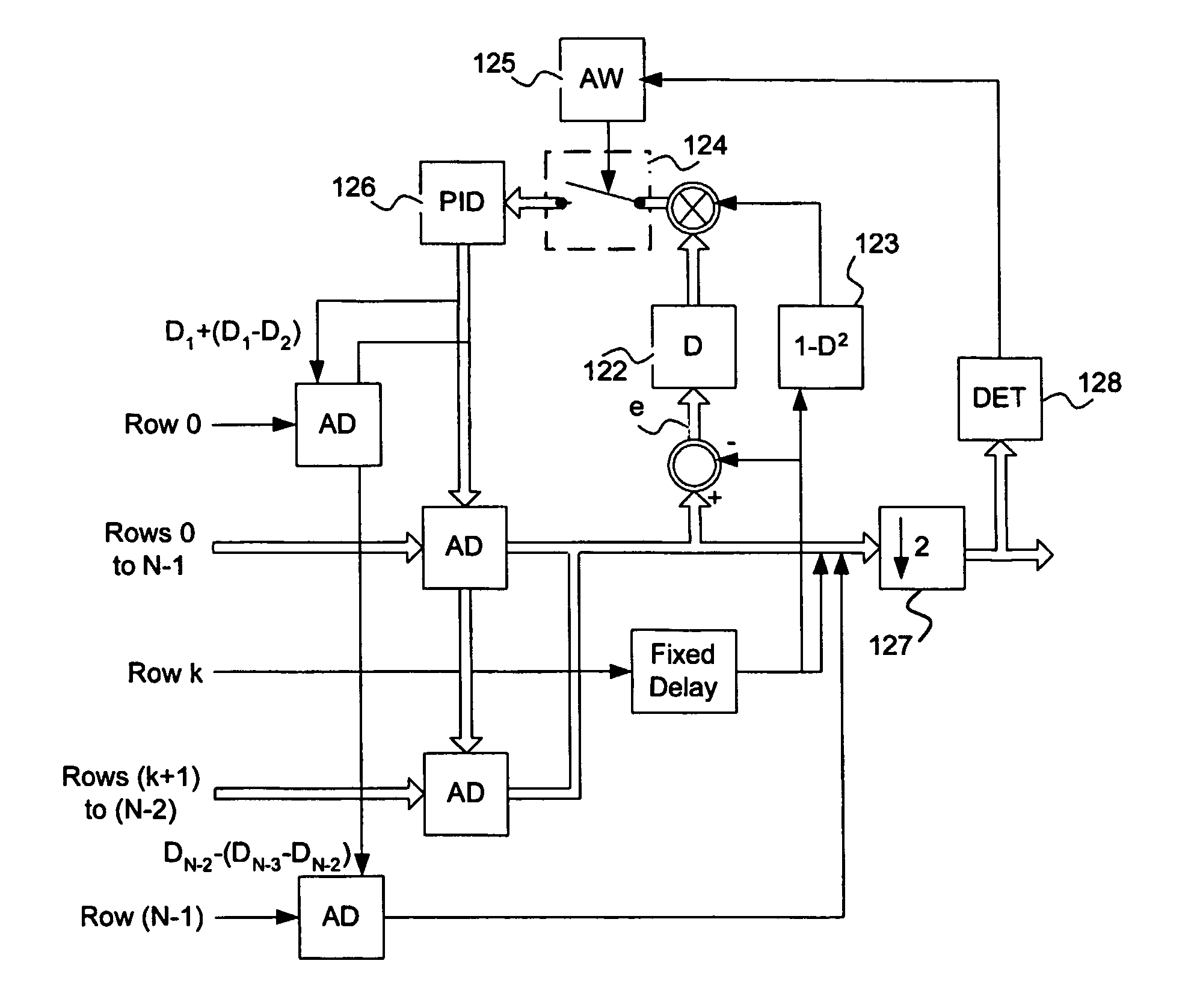
[0041] The present invention relates to a method and device for synchronizing signals coming from a set of data channels of a two dimensional optical read-out system.

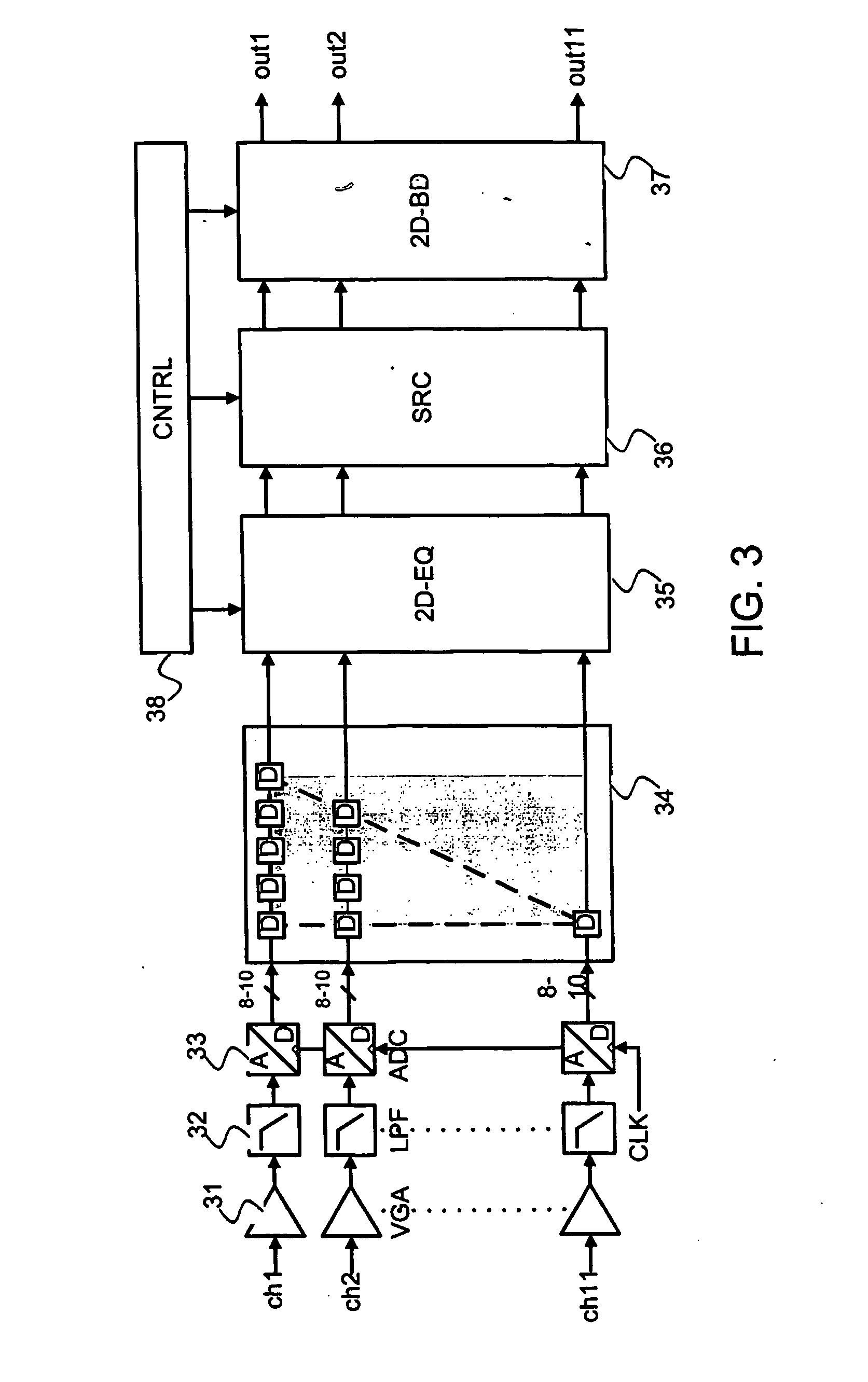
[0042] Said invention is depicted in the following description in the case of data storage on optical carriers. However, it will be apparent to a person skilled in the art that said invention stays also applicable to equivalent systems such as, for example, two-dimensional magnetic recording systems when magnetic read / write heads need a slanted arrangement with respect to the tracks due to a minimum distance between the heads, for example due to processing limitations.

[0043] It has as an objective to make the synchronization device an independent operating signal processing block, independent from further timing recovery and sample-rate converter blocks.

[0044] Two-dimensional optical recording system are subjected to a large inter symbol interference ISI in both radial and tangential direction. This means, on the one...


PUM


Abstract

The present invention relates to a method for synchronizing the signals coming from a set of data channels of a two dimensional optical read-out system. Said synchronization method comprises a step of cross-correlating the signals of a pair of adjacent channels for determining a relative phase delay between said adjacent channels. It also comprises a step of iterating the cross-correlation step for the different pair of adjacent channels of the set of data channels. It finally comprises a step of compensating for the relative phase delays thus obtained in order to align the signals from adjacent channels with each other. The present invention is based on, for example, the use of the optical cross talk existing between adjacent channels in a cross correlator that is able to determine the relative phase between two adjacent channels.

Description

FIELD OF THE INVENTION [0001] The present invention relates to a method for synchronizing signals coming from a set of data channels of a two dimensional optical read-out system. [0002] The present invention also relates to a device implementing such a synchronization method and to a two-dimensional optical recording and / or reproducing apparatus including such a device. [0003] This invention is, for example, particularly relevant for data storage on optical carriers. BACKGROUND OF THE INVENTION [0004] In a conventional two-dimensional optical recording system, bits are stacked on a storage medium on a regular two-dimensional lattice and no distinction can be made between the tangential and radial direction. The system is ideally isotropic. [0005] In practice, the two-dimensional area of a two-dimensional record carrier is organized in a slightly different way: the two-dimensional area is filled with successive revolutions of a so-called “broad spiral”. In such a broad spiral, the ta...

Claims


Application Information

Patent Timeline
IPC IPC(8): G11B20/14G11B20/10G11B27/30
CPCG11B20/10009G11B2020/1249G11B20/10222G11B20/10G11B27/30
Inventor IMMINK, ALBERT HENDRIK JANCOENE, WILLEM MARIE JULIA MARCELBERGMANS, JOHANNES WILHELMUS MARIARIANI, JAMAL
Owner KONINKLIJKE PHILIPS ELECTRONICS NV
Features
  • Generate Ideas
  • Intellectual Property
  • Life Sciences
  • Materials
  • Tech Scout
  • Unparalleled Data Quality
  • Higher Quality Content
  • 60% Fewer Hallucinations
Learn More