Fuel cell system and control method of fuel cell system

a fuel cell and control method technology, applied in the field of fuel cell systems, can solve the problems of insufficient power, deterioration of the electrolyte membrane, and lower power generation performan

Active Publication Date: 2007-02-01
HONDA MOTOR CO LTD
View PDF5 Cites 54 Cited by
  • Summary
  • Abstract
  • Description
  • Claims
  • Application Information

AI Technical Summary

Benefits of technology

[0019] According to this embodiment, it is possible to use an appropriate amount of scavenging gas to scavenge

Problems solved by technology

However, when power generation is stopped, a conventional fuel cell system scavenges the water for a pre-determined period.
Therefore, there is a problem that unnecessarily too long scavenging causes the electrolyte membrane to deteriorate so as to lower performance of the power generation.
Moreover, since t

Method used


Image

  • Fuel cell system and control method of fuel cell system
  • Fuel cell system and control method of fuel cell system
  • Fuel cell system and control method of fuel cell system

Examples


first embodiment

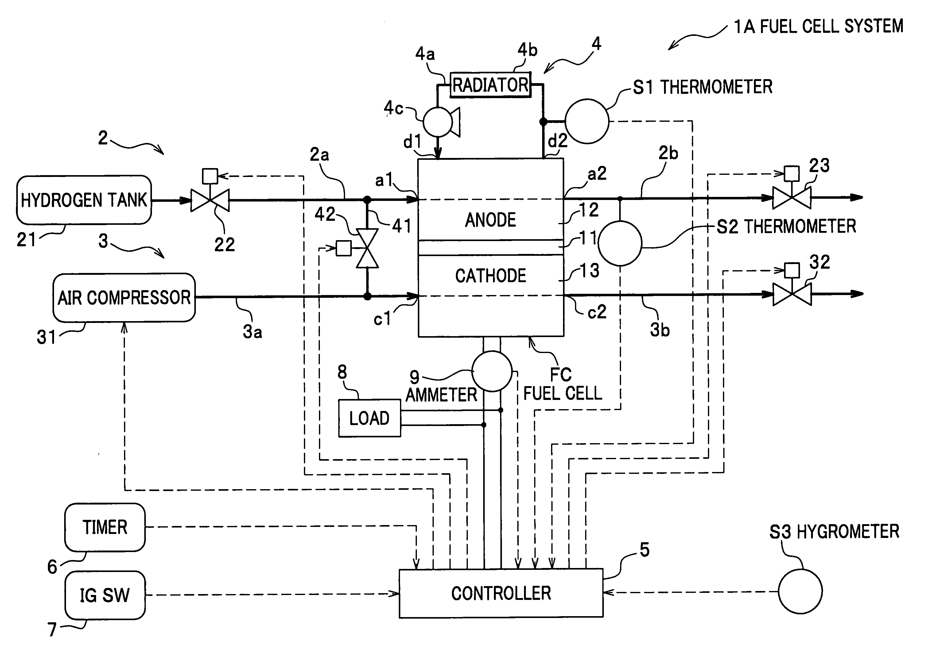
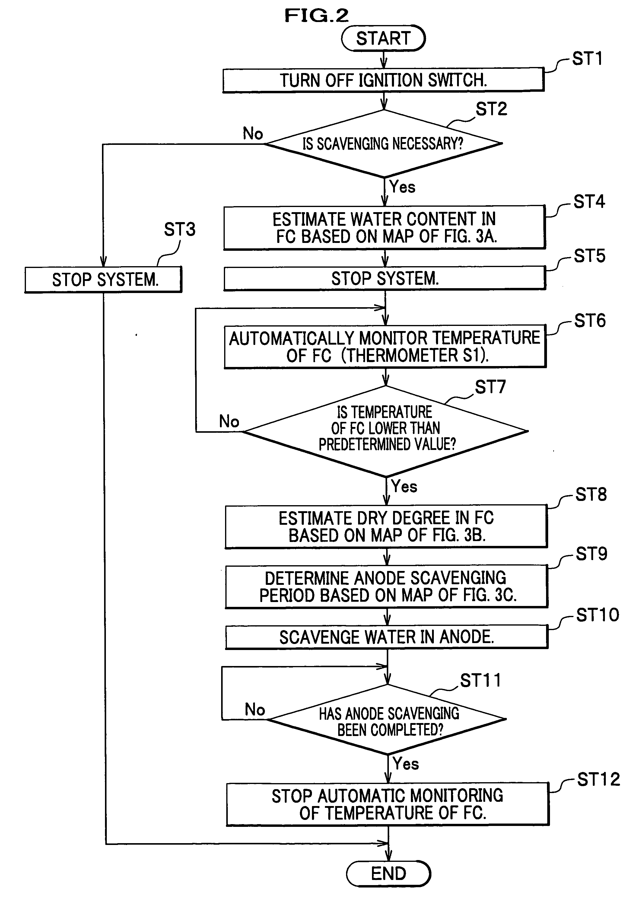
[0046] The following description will be given to a case of a vehicle as an example. However, the present invention is not limited to this and may be also applied to a ship, an aircraft, and so on, as well as, to a stationary fuel cell system. Moreover, the following embodiment will be described in a case of being applied to anode scavenging.

[0047] A fuel cell system 1A of a first embodiment includes a fuel cell FC, an anode system 2, a cathode system 3, a cooling system 4, a controller 5, and so on.

[0048] A fuel cell with PEM (Proton Exchange Membrane), which is solid polymer, is employed as the fuel cell FC. An electrolyte membrane 11 is sandwiched between an anode 12 and a cathode 13 which include a predetermined catalyst, to form a membrane electrode assembly (MEA). The membrane electrode assembly is further sandwiched between a pair of electrically conductive separators (not shown) to form a cell. Then, a plurality of the cells are stacked to form a stack of the fuel cells FC...

second embodiment

[0078]FIG. 5 is a configuration diagram showing a whole fuel cell system according to a second embodiment. FIG. 6 is a flow chart showing processes of scavenging in the second embodiment. FIG. 7A is a map showing relationship between an integrated value of generated electric current and a water content in a fuel cell. FIG. 7B is a map showing relationship between a power generation stop period and the water content in the fuel cell. FIG. 7C is a map showing relationship between the water content in the fuel cell and a cathode scavenging period.

[0079] In a fuel cell system 1B according to the second embodiment, a thermometer (a temperature detector or a temperature detecting means) S4 is provided in a side of the cathode gas discharge pipe 3b in stead of the thermometer S2 in the fuel cell system 1A (see FIG. 5). Description of the other parts of the configuration, which is similar to the first embodiment, will be omitted. Therefore, only effects of the second embodiment will be exp...


PUM


Abstract

A fuel cell system is provided which estimates a water content in a fuel cell based on a predetermined map using an integrated value of electric current generated by the fuel cell (ST4) before power generation is stopped (ST5). When a temperature of the fuel cell has fallen lower than a predetermined value (ST7) after the power generation is stopped (ST5), the fuel cell system determines a dry degree in the fuel cell (ST8) and an anode scavenging period (ST9) based on predetermined maps. Scavenging is performed in an anode in the fuel cell for the anode scavenging period (ST10).

Description

CROSS REFERENCE TO RELATED APPLICATIONS [0001] This application claims the foreign priority benefit under Title 35, United States Code, §119 (a)-(d) of Japanese Patent Application No. 2005-215291, filed on Jul. 26, 2005 in the Japan Patent Office, the disclosure of which is herein incorporated by reference in its entirety. BACKGROUND OF THE INVENTION [0002] 1. Field of the Invention [0003] The present invention relates to a fuel cell system which can start operating in low temperature conditions and a control method of the fuel cell system. [0004] 2. Description of the Related Art [0005] For instance, a PEM (Proton Exchange Membrane) fuel cell using a solid polymer as an electrolyte membrane is generally employed for a fuel cell stack in a fuel cell electric vehicle. This kind of fuel cell stack is a stack of plural cells each of which is formed by a membrane electrode assembly (MEA) sandwiched between a pair of separators. Moreover, the membrane electrode assembly is formed by an e...

Claims


Application Information

Patent Timeline
IPC IPC(8): H01M8/04
CPCH01M8/04231Y02E60/50H01M8/04343H01M8/04358H01M8/04388H01M8/04402H01M8/04432H01M8/04492H01M8/045H01M8/04507H01M8/04589H01M8/04753H01M8/04761H01M8/04768H01M8/04253
Inventor OGAWA, JUMPEIWAKE, CHIHIROMIYATA, KOICHIRO
Owner HONDA MOTOR CO LTD
Why Eureka
Try Eureka