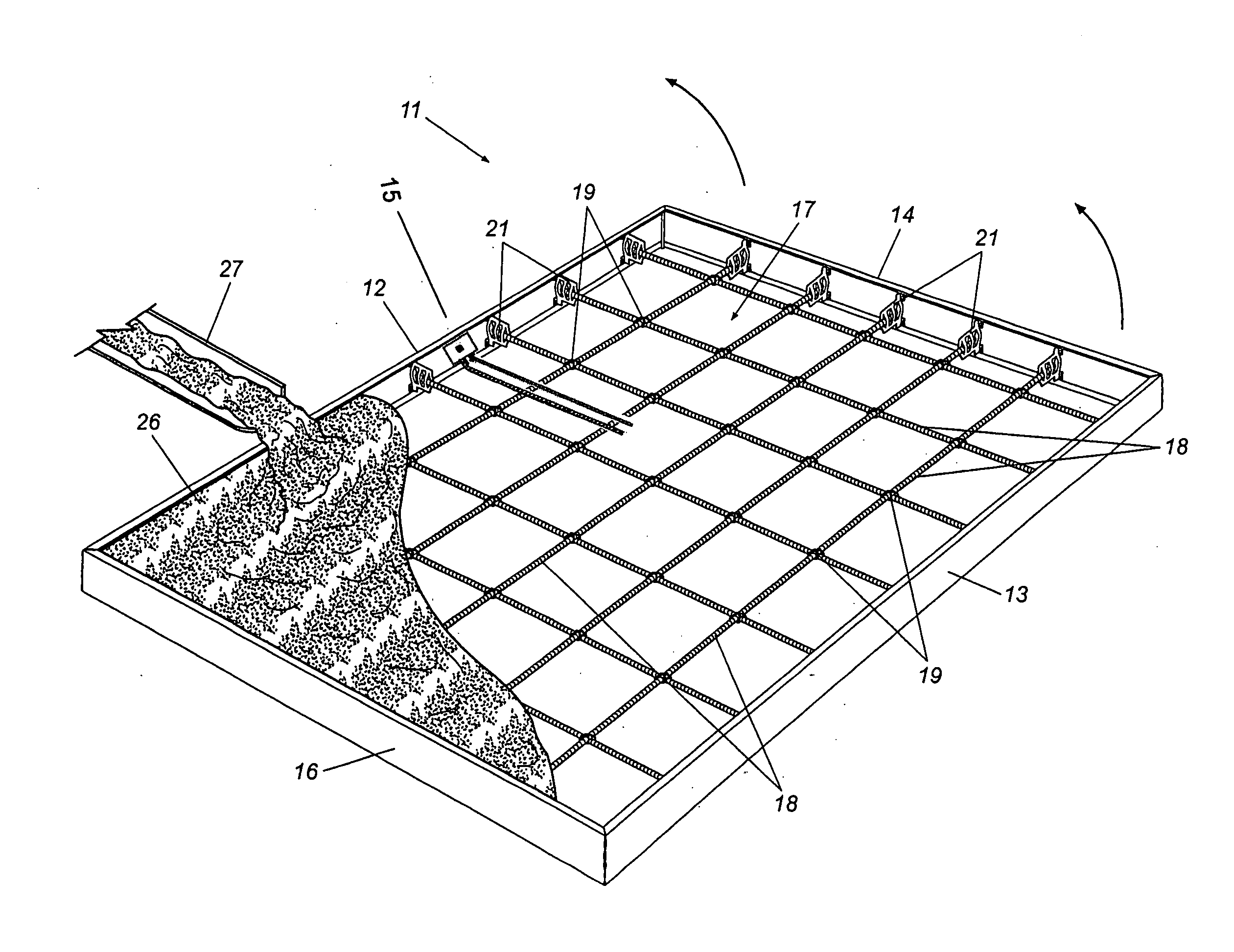
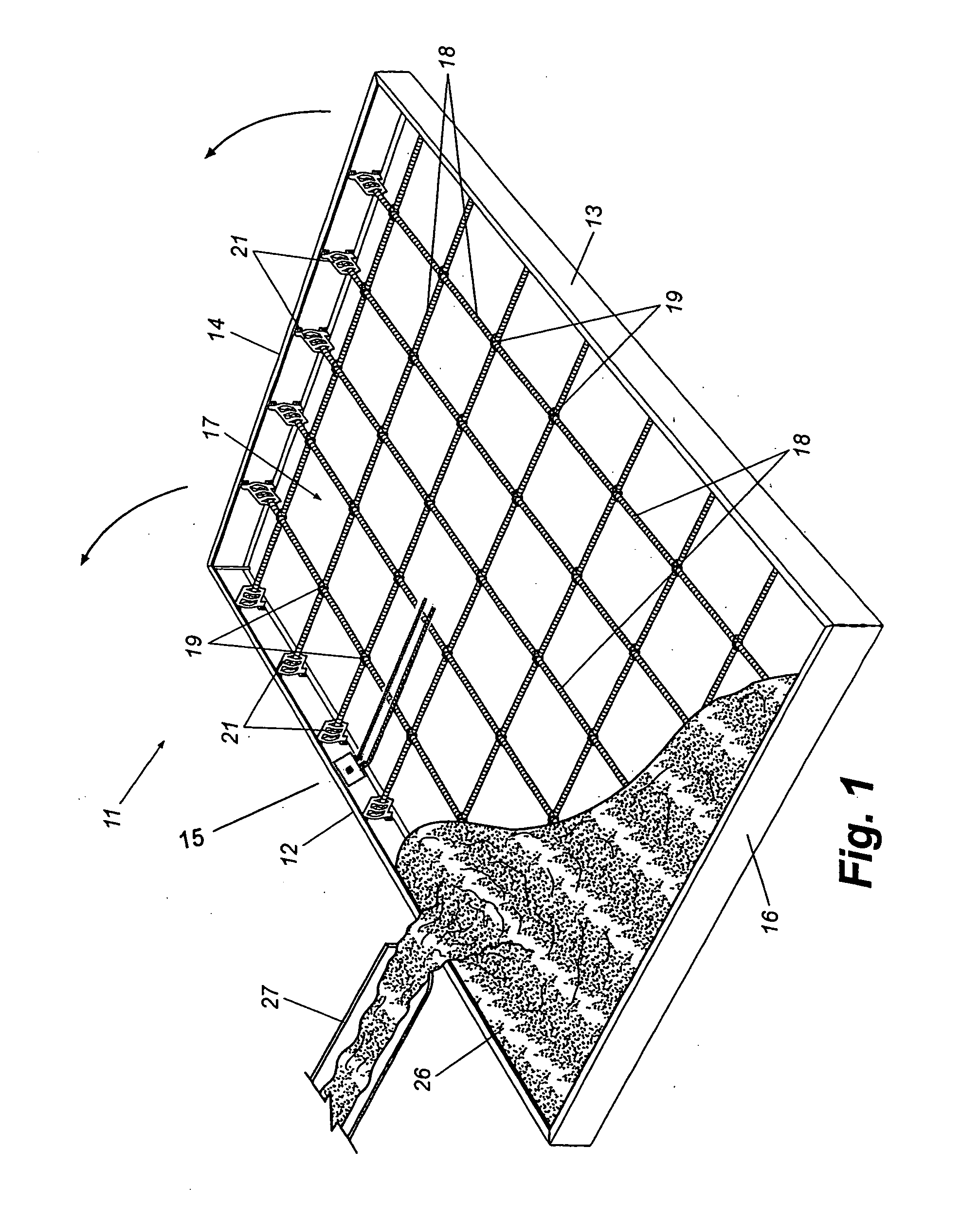
[0008] Briefly described, the present invention in a preferred embodiment thereof, comprises an improved form for fabricating tilt-up concrete wall sections and an
improved method of fabricating tilt-up concrete wall sections using the form. The for generally C-shaped or channel-shaped roll formed sheet
metal frame members that are welded together at their ends to define the shape of the form, which may be rectangular for many applications but that also may take on other shapes according to applications specific requirements. A matrix or mat of crisscrossed rebar is disposed in the form to provide reinforcement when concrete is poured into the form during fabrication of a concrete wall section. Each rebar of the matrix extends between opposed frame members of the form and is
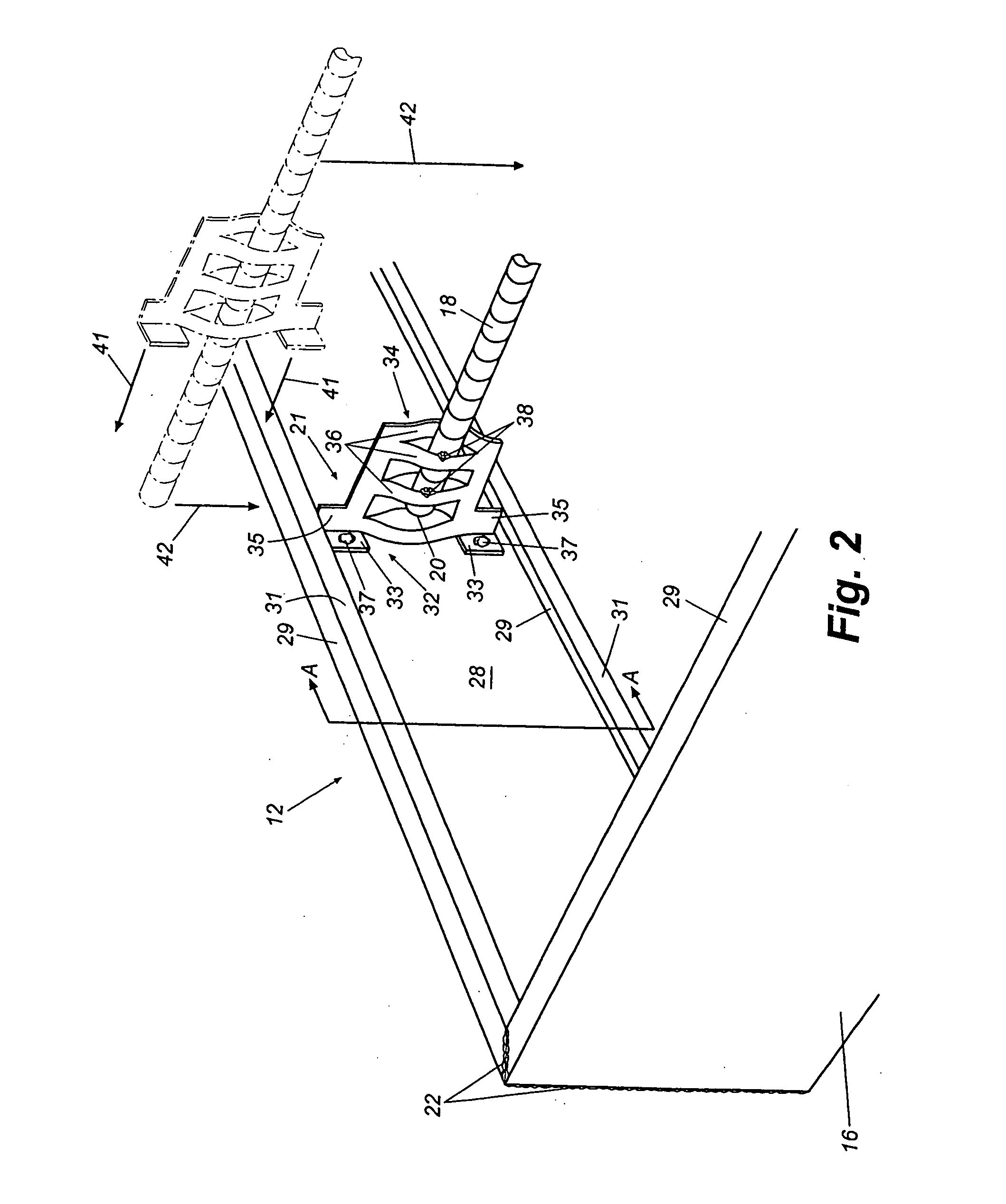
cut to be short enough to slip into the mid-portion of the form past the inwardly extending flanges of the C-shaped frame members. A unique bracket is slidably disposed on the ends of at least some of the rebars of the rebar mat and each bracket is spot welded to the corresponding frame member and to its rebar. This configuration establishes
structural integrity of the
assembly. Brackets may be disposed on the ends of each rebar or just on the ends of selected ones of the rebars as necessary to hold the reinforcing mat in place and to establish the desired
structural integrity. The form is fabricated at a remote manufacturing facility as follows. First, the roll formed sheet
metal frame members are
cut to size and welded together at their ends to define a frame of the appropriate size an shape. The generally channel-shaped frame members are oriented with their open or channeled sides facing inwardly toward the middle or the form. In other words, the flanges on the edges of the frame members face inwardly toward each other and thus may be referred to as inwardly extending flanges. Down turned lips preferably are formed along the edges of the flanges to add strength and rigidity.
[0010] The crisscrossed rebar mat is then constructed by arranging individual rebars and
welding them together at their intersections. A bracket is slid onto the ends of each rebar until the rebar ends protrude from the base of the bracket. With the mat constructed and brackets installed, the entire rebar mat can be positioned in the form. Since the rebars are
cut short as mentioned above, the entire rebar mat slips easily past the inwardly extending flanges of the frame members and into the middle of the form. With the rebar mat properly positioned within the form, the brackets on the ends of the rebars are slid toward the frame members until the base of each bracket rests against the outside panel of the frame member between its inwardly projecting flanges. The base portions of the brackets are configured to extend between the flanges of the frame members, thereby automatically entering the rebar mat in the middle of the form. The bases of the brackets are then spot welded to the frame members and the end of each rebar is spot welded to its respective bracket to complete the form. It will thus be seen that the rebar mat is automatically centered and held in place by the brackets. Further, since the rebar mat is welded together and to the brackets, and the brackets are welded to the frame members, the completed form is strong and rigid and maintained in its proper shape by the installed rebar mat.
[0011] Since the forms of the present invention are lightweight and rigid, they may be handled, shipped to the jobsite where they are to be used to fabricate concrete wall sections, and unloaded at the job site without fear of the forms becoming warped or deformed. Once at the jobsite, the forms are laid flat on a
casting surface, such as a concrete slab, preferably near the location where concrete wall sections are to be erected. A unique pocket form or void form is inserted into the opening of the unique anchor prior to adding the wet concrete. The shape of the unique pocket form automatically positions the face toward the wall panels surface and holds it in place. The unique pocket form also has small tabs on its face which will stand erect and protrude above the concrete surface to aid in identifying the unique anchor locations after the concrete is set and cured. The forms are then filled with concrete from a concrete
truck, a pump
truck, or other source. Again, since the brackets are welded to the frame members and the rebars of the mat welded to the brackets the rebar mat ties the framing members together and prevents them from bowing or bulging outwardly under the pressure of the wet concrete. Accordingly, no further reinforcing blocks or other reinforcement is required prior to pouring the concrete into the forms as is common in prior art systems.
[0014] Exact alignment between connection elements of the finished concrete wall panel and the to-be-connected adjacent
structural element no longer exists with the described invention because the wall panel connection with the unique anchor does not require the adjacent element to have a pre-placed attachment. This alleviates the need for exacting match-up tolerances at connection points where the unique anchor is used, the connection point is determined after the finished concrete wall panel is in position and the unique anchor provides the exact hole placement after proper wall positioning is achieved. The remote site welded placement fabrication of the unique anchor ensures it will not move during the application of wet concrete at the work-site which helps eliminate misplaced, lost or omitted anchors. Any required welding is completed during fabrication at the remote site before being shipped to the work-site, therefore no special welding equipment or welding skills would be required at the work-site.
[0015] All of the elements of the form remain with the finished concrete wall sections and become a part of the finished wall. Accordingly, no disassembly of the form is required after the concrete cures and no waste that must be discarded is produced.
[0016] Thus, a unique and improved tilt-up concrete wall section form is now provided that is quickly, accurately, and efficiently fabricated at a remote manufacturing facility. The form is rigid and self reinforcing and may be handled and shipped to a job site, where it is simply laid on a
casting surface and filled with wet concrete without the need for on-site construction or ancillary reinforcing members to prevent bowing of the form. When the concrete cures to form a wall section, the entire structure, form and all, is tilted up and attached to form a concrete wall without any disassembly or waste and without connection match-up difficulties or special work-site welding. The method of fabricating tilt-up concrete walls using forms of the present invention is efficient and substantially quicker than with prior art tilt-up wall systems. These and other features, objects, and advantages of the form and fabrication method of the invention will become more apparent upon review of the detailed description set forth below when take in conjunction with the accompanying drawing figures, which are briefly described as follows.

