Structural window in composite sandwich beam

US20070028553A1Inactive Publication Date: 2007-02-08KIRBY RICHARD ALBERT

Image

  • Structural window in composite sandwich beam
  • Structural window in composite sandwich beam
  • Structural window in composite sandwich beam

Examples


Embodiment Construction

FIG. 1 to FIG. 6

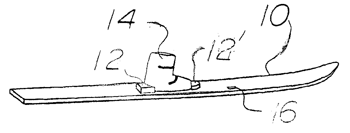
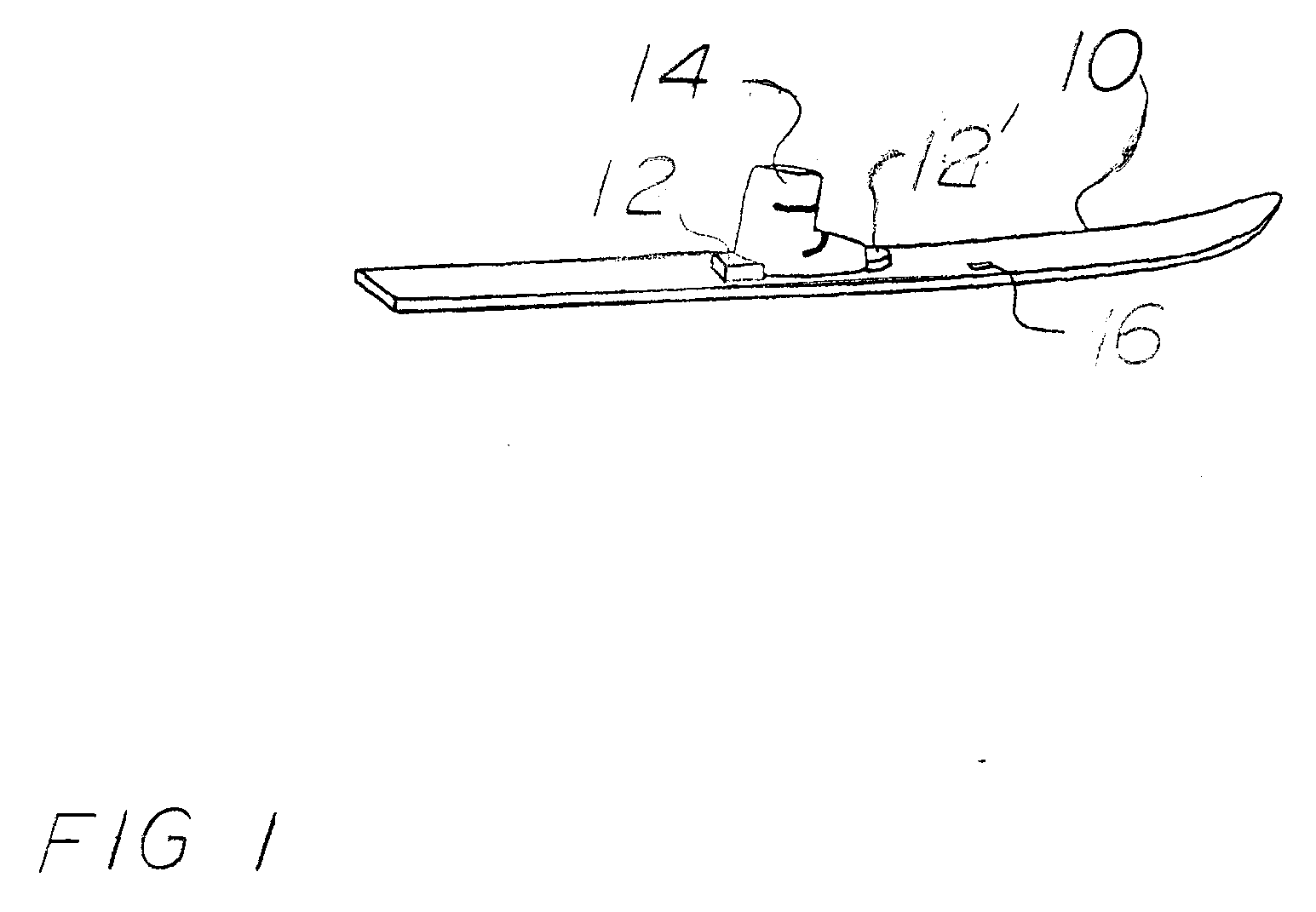
[0071] A preferred embodiment of a structural window is shown in FIG. 1 where the composite sandwich beam is a ski 10. FIG. 1 shows a location of the structural window 16 relative to a ski binding 12 and 12′ and a ski boot 14 in ski 10.

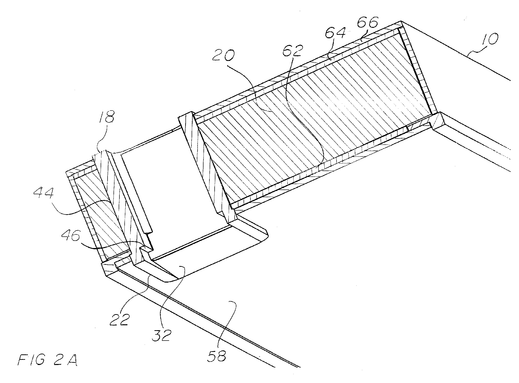
[0072] A cross-section of structural window 16 is illustrated in FIG. 2A (lateral cross-section) and FIG. 2B (longitudinal cross-section). Structural window 16 has a window body 18 made of a structurally strong material. The preferred embodiment uses 30% glass filled polyamide, but ABS, polyethylene, UHMW polyethylene, aluminium or another structurally strong material could be used. Window body 18 can be hollow as shown, or can be solid. In the preferred embodiment, the wall thickness of window body 18 is 2 mm thick although other wall thicknesses could be used. In the preferred embodiment, window body 18 extends 1 mm above the upper surface of ski 10 which is made up of an upper structural skin 64 and a cosmetic upper surface 66, alt...


PUM


Abstract

A window for installation in a sandwich composite beam shown in FIG. 2B that contains window body (18), tabs (22), and a means of attaching the tabs to the composite sandwich beam. The means of attaching tabs (22) could be an interlocking mechanism such as dowel interlock feature (48) in FIG. 3A. The window body (18) protects the composite beam core from moisture. Structural webbing (24) allows the strength and flexibility of the window to be adjusted to match the beam it is being installed in. The structural window also provides a platform for an imaging system shown in FIG. 6 including illumination source (36), collimating lens (34), and imaging lens (38).

Description

CROSS-REFERENCE TO RELATED APPLICATIONS [0001] This patent application is related to U.S. Pat Application 20,040,075,737 by the same inventor. FEDERALLY SPONSORED RESEARCH [0002] Not applicable SEQUENCE LISTING OR PROGRAM [0003] Not applicable BACKGROUND OF THE INVENTION [0004] 1. Field of Invention [0005] This invention relates to a structural window in a composite sandwich beam such as a ski or the wing of a composite airplane. [0006] 2. Prior Art [0007] Modern skis are almost universally made as composite sandwich beams with a core of wood, foam or similar material and a skin. The skin contains structural materials with high tensile strength, a base and cosmetic sides and top. The structural materials for the skin could be aluminium, fiberglass cloth, carbon fiber cloth, or other material with a high tensile strength. A combination of these materials can also be used, e.g. aluminium and fiberglass together. The base material is often Ultra High Molecular Weight (UHMW) polyethylen...

Claims


Application Information

Patent Timeline
08 Feb 2007
Publication
US20070028553A1
IPC
E04C3/30
CPC
A63C5/06; B64C3/20; A63C5/128
Inventors
KIRBY, RICHARD ALBERT