Hybrid evaporator

a hybrid evaporator and evaporator technology, applied in indirect heat exchangers, lighting and heating apparatus, stationary conduit assemblies, etc., can solve the problems of cooling capacity decline, non-uniform air temperature distribution, and further exacerbated non-uniform discharge air temperature in such evaporators, so as to reduce the drop in pressure and maximize the surface area of the plate

Active Publication Date: 2007-02-08
MAHLE INT GMBH
View PDF11 Cites 10 Cited by
  • Summary
  • Abstract
  • Description
  • Claims
  • Application Information

AI Technical Summary

Benefits of technology

[0009] The subject invention overcomes the limitations of the art by providing an evaporator which utilizes U-channel plates in combination with various configurations of dual cup and single cup plates. The U-channel plates are utilized to define one or more of the final refrigerant passes in the evaporator, which aids in the distribution of the small quantity of liquid refrigerant that typically remains in those passes as the refrigerant vaporizes and its quality approaches unity. The dual and single cup plates are utilized in passes upstream from the U-channel plates to reduce the drop in pressure that would otherwise occur on the refrigerant side if U-channel plates were used throughout the evaporator. Extending the fins to the upper edges of the U-channel plates maximizes the surface area of the plates available for heat exchange in the final refrigerant passes.

Problems solved by technology

Unfortunately, because the refrigerant absorbs heat from the air, the cooling capacity of the refrigerant decreases with each additional pass the refrigerant makes.
The problem of non-uniform temperature of the discharge air is further exacerbated by the manner in which an evaporator core is designed.
For instance, non-uniform air temperature distribution occurs in such evaporators when a vehicle in which the evaporator is installed accelerates from rest.
In this situation, the compressor of the climate control system quickly draws refrigerant out of the evaporator, causing high refrigerant superheats to occur within the last passes of the evaporator.
However, the cooling capacity of such tubes is compromised by the increased pressure drop that occurs on the refrigerant side of the tubes, which is caused by the reduced cross-sectional area of the tubes available for refrigerant flow.
Although evaporators that utilize dual cup tubes to effectively create two cores through which the refrigerant flows in series first through one core and then the other achieve improved temperature spreads and greater cooling capacity than evaporators formed from U-channel tubes, increasing movement towards evaporator cores with smaller depths, necessitated by space constraints, has eroded these benefits.
The smaller the core depth, the narrower the cross-sectional area of the tubes through which the refrigerant must flow, and the greater the refrigerant pressure drop, which has a negative impact on the cooling capacity of the evaporator core.

Method used


Image

  • Hybrid evaporator
  • Hybrid evaporator
  • Hybrid evaporator

Examples


Embodiment Construction

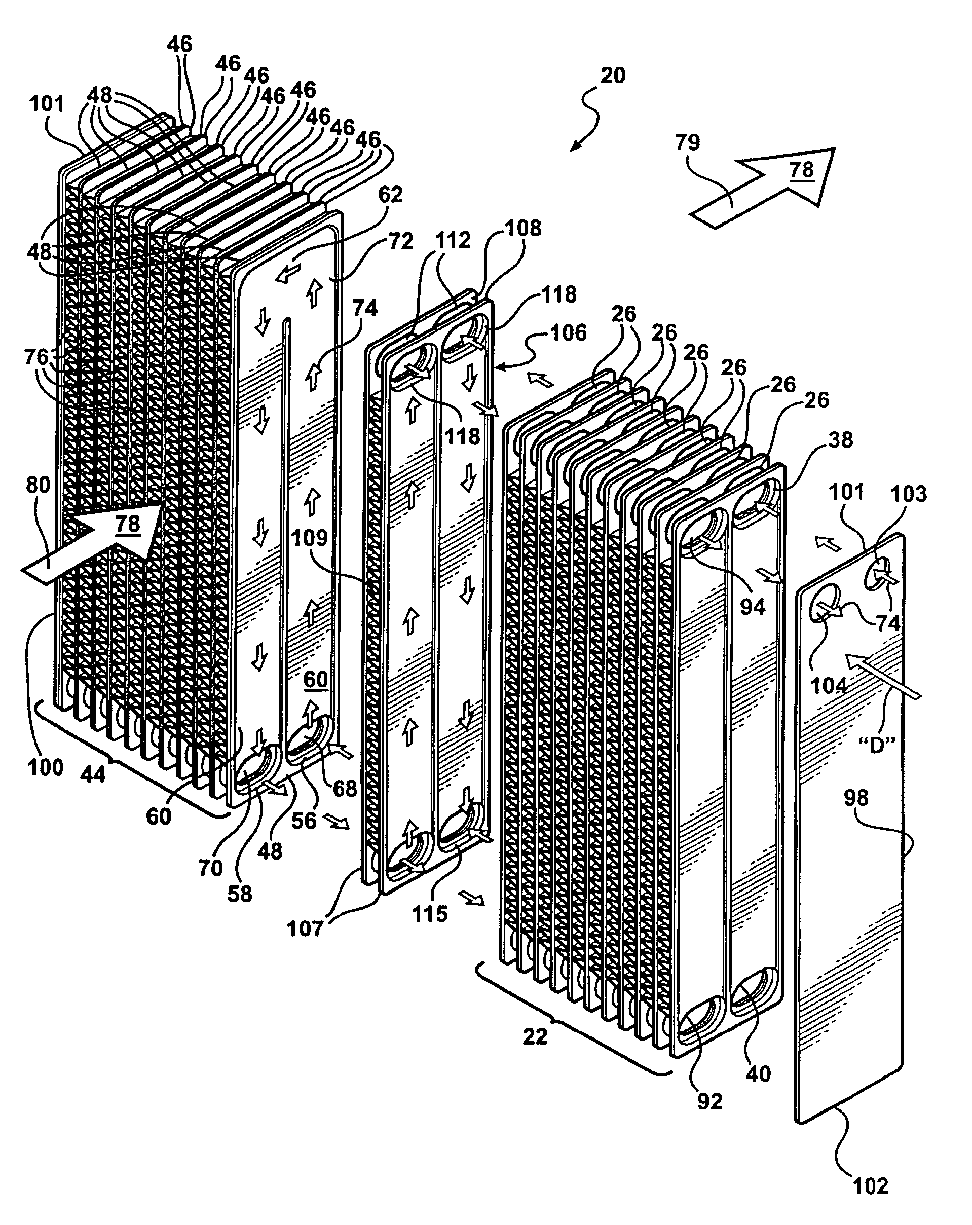
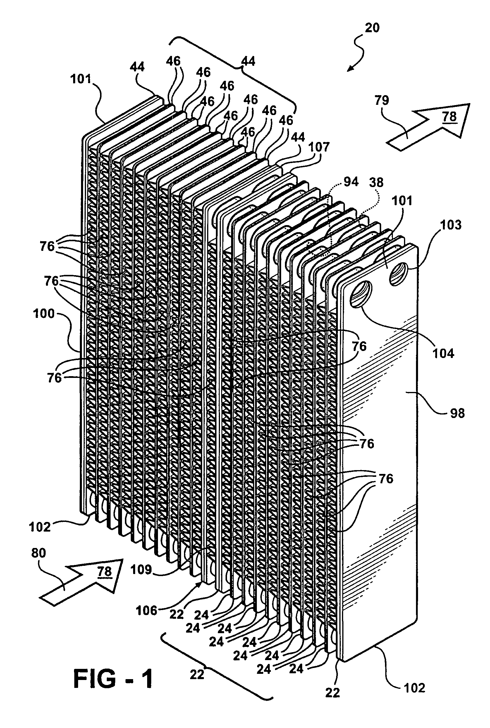
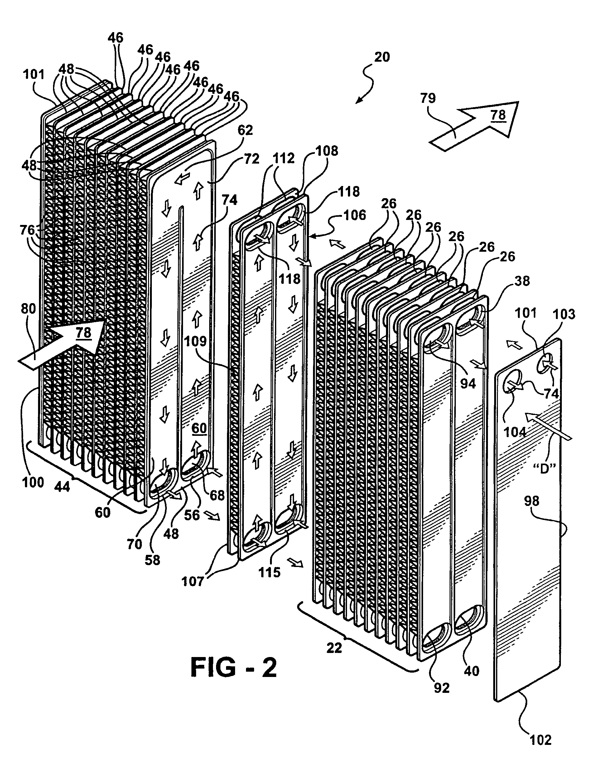
[0024] Referring to the Figures, wherein like numerals indicate like or corresponding parts throughout the several views, a laminate-type evaporator is generally shown at 20 in FIGS. 1 through 3. The evaporator 20 includes a plurality of first tube plates 22 (dual cup tube plates) stacked together in adjacent pairs 24. As is best shown in FIG. 4, each first plate 22 includes first and second tubular projections 26, 28 and a first recess 30. The first plate 22 also has an exterior surface 32. The first recess 30 extends between the first and second tubular projections 26, 28. The first and second tubular projections 26, 28 define respective apertures 34, 36 through the plate 22. The projections 26, 28 also extend from the plate 22 in the same direction as the first recess 30.

[0025] Referring to FIGS. 1 and 2, the adjacent pairs 24 are positioned in abutting engagement with one another such that the first tubular projections 26 define a first tank 38 and the second tubular projection...


PUM


Abstract

A laminate-type evaporator includes U-channel plates in combination with various configurations of dual cup and single cup plates, to control refrigerant pressure drop and achieve enhanced temperature spreads within the evaporator. The U-channel plates define one or more of the final refrigerant passes in the evaporator, and the dual cup and single cup plates define refrigerant passes upstream therefrom. Fins are disposed between adjacent plate pairs and extend to selected end edges of the U-channel plates to maximize the surface area available for heat exchange in the final refrigerant passes.

Description

FIELD OF THE INVENTION [0001] This invention relates to a heat exchanger, and more particularly, to an evaporator for the climate control system of a motor vehicle. DESCRIPTION OF THE RELATED ART [0002] Evaporators are well known in the art, and typically include a plurality of tubes having interiors through which refrigerant flows. Thermal energy, or heat, exchange occurs between ambient air flowing outside the tubes and the refrigerant flowing within. To enhance the amount of heat exchanged between the air and refrigerant, multiple fins are disposed between the adjacently positioned tubes. The fins are placed in contact with selected exterior surfaces of the tubes. This increases the surface area available for heat transfer from the air to the refrigerant circulating within the tubes, which in turn cools and dehumidifies the air as it flows across the exterior of the evaporator. [0003] Heat transfer from the air to the refrigerant is further enhanced by routing the refrigerant to ...

Claims


Application Information

Patent Timeline
Patent Type & Authority Applications(United States)
IPC IPC(8): F28D1/02
CPCF28D1/0333Y10S165/465F28D2021/0064F28D1/0341
Inventor MEHENDALE, SUNIL S.LIPA, SCOTT B.
Owner MAHLE INT GMBH
Why Eureka
Try Eureka