Multiple electroluminescent lamp driver

a technology of electroluminescent lamps and drivers, applied in the direction of electroluminescent light sources, electroluminescent lamp usage, electric lighting sources, etc., can solve the problem of not being able to independently

Inactive Publication Date: 2007-02-08
IEE INT ELECTRONICS & ENG SA
View PDF9 Cites 19 Cited by
  • Summary
  • Abstract
  • Description
  • Claims
  • Application Information

AI Technical Summary

Benefits of technology

[0006] It is an object of the present invention to provide a device for driving at least two electroluminescent lamps, with w

Problems solved by technology

The problem with conventional drivers for EL lamps with low complexity on the high-voltage supply side and with a single high-voltage supply is that it is not possible to independently drive two separate EL lam

Method used


Image

  • Multiple electroluminescent lamp driver
  • Multiple electroluminescent lamp driver
  • Multiple electroluminescent lamp driver

Examples


Embodiment Construction

[0024] Preferred embodiments of an EL lamp driver in accordance with the invention will now be described. In the present embodiments, the driver is designed to be used to drive a dual (or multiple) EL lamp.

[0025] In the following description the same and / or equal and / or similar elements can be denoted with the same reference numerals.

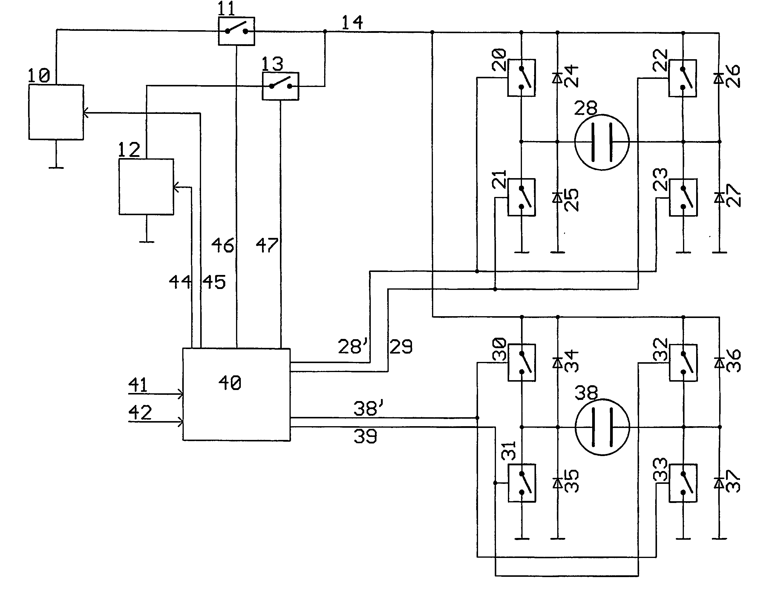
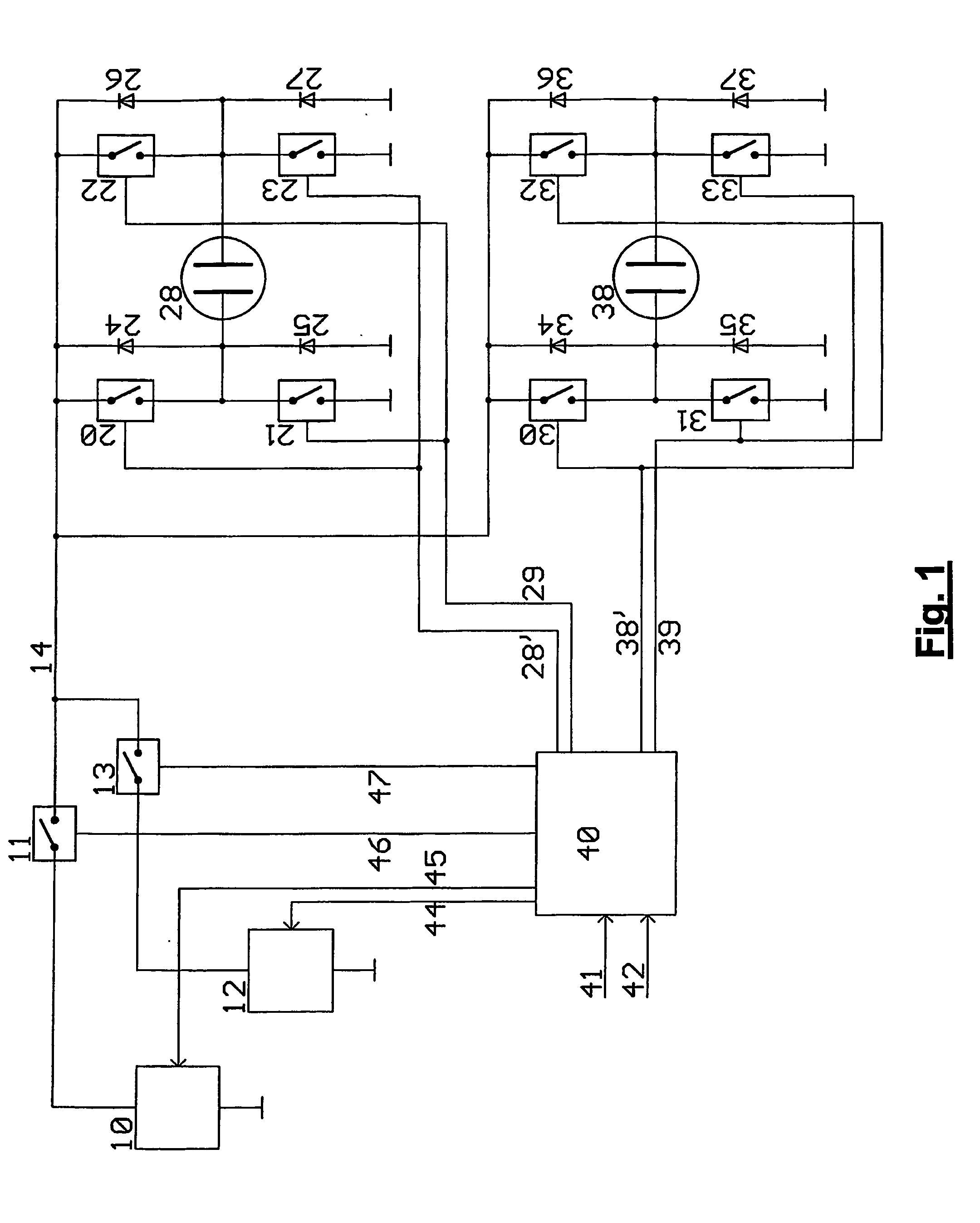
[0026]FIG. 1 shows an electroluminescent lamp driver for two EL lamps 28 and 38 with an open loop control. The driver comprises high voltage charging means 10, discharging means 12, one H-bridge 20-23 and 30-33 for each of the two EL lamps 28 and 38, and a controlling device 40.

[0027] The controlling device 40 receives input control voltages at two setpoint inputs 41 and 42 in order to control the brightness of the two EL lamps 28 and 38.

[0028] The input control voltages received at input 41 and 42 correspond to the desired luminance brightness for the EL lamps 28 and 38, respectively.

[0029] The controlling device 40 generates control signals 44-47...


PUM


Abstract

The invention relates to an electroluminescent (EL) lamp driver for controlling the luminescent brightness of at least two EL lamps (28, 38), wherein the driver I is adapted to receive at least two setpoint values corresponding to luminescent brightness of the EL lamps and to create charge waveforms (128, 138) in accordance with the received setpoint values for charging or discharging the EL lamps (28, 38).

Description

FIELD OF THE INVENTION [0001] The present invention relates to a device for driving at least two electrolumines-cent lamps. BACKGROUND OF THE INVENTION [0002] Electroluminescence (EL) is the non-thermal conversion of electrical into luminous energy. Well known electroluminescent devices are light emitting diodes (LEDs), in which light is generated by electron-hole pair recombination near a pn junction. Also known are electroluminescent lamps (EL lamps) which have become a popular light source for backlighting Liquid Crystal Displays. [0003] In EL Lamps, light is generally generated by impact excitation of a light emitting center (called the activator) by high energy electrons in materials like ZnS:Mn. The electrons gain their high energy from an high electric field. Therefore, this type of electroluminescence is often called high field electroluminescence. Thus, a high voltage is required for driving EL lamps. [0004] The problem with conventional drivers for EL lamps with low comple...

Claims


Application Information

Patent Timeline
IPC IPC(8): H05B37/02H05B41/08H05B44/00
CPCY02B20/325H05B33/08Y02B20/30H05B44/00
Inventor LAMESCH, LAURENT
Owner IEE INT ELECTRONICS & ENG SA
Why Eureka
Try Eureka