Power manager and power managing method for battery-powered application

Active Publication Date: 2007-02-08
ANALOG DEVICES INT UNLTD
View PDF16 Cites 86 Cited by
  • Summary
  • Abstract
  • Description
  • Claims
  • Application Information

AI Technical Summary

Benefits of technology

[0006] Current in the circuit path may be monitored by a third circuit, and in response, the switching regulator controlled to limit the current within a current limit. The third circuit is preferably configured to obtain an averaged current in the circuit path so as to compare the averaged current with the current limit. The current in the circuit path may be limited when it exceeds the current limit, causing a voltage in the circuit path to drop. When the voltage in the circuit path drops to just above the level of the battery voltage, the first circuit enters dropout from the circuit path. That is, the first circuit may be unable to deliver its entire programmed charge current to the battery. In this case, since the first circuit is unable to regulate charge current it becomes a resistive element seeking its lowest possible resistance. Due to the nature of a resistive element, the charge current into the battery is automatically reduced to only the amount that can be supported given the current limited switching regulator and the external load. Likewise, when the voltage in the circuit path falls below battery voltage, current from the battery can be provided to the load through the first circuit. The first circuit may include, or be configured to operate as, a diode to provide the current from the battery to the load. An auxiliary diode or ideal diode with a separate conduction path may also be included to deliver current from VBAT to VOUT.
[0007] In another aspect, a power

Problems solved by technology

The current in the circuit path may be limited when it exceeds the current limit, causing a voltage in the circuit path to drop.
That is, the first circuit may be unable to deliver its entire programmed charge current to the battery.
In this case, since the first circuit is unable to regulate charge current it becomes a resistive element seeking its

Method used


Image

  • Power manager and power managing method for battery-powered application
  • Power manager and power managing method for battery-powered application
  • Power manager and power managing method for battery-powered application

Examples


Embodiment Construction

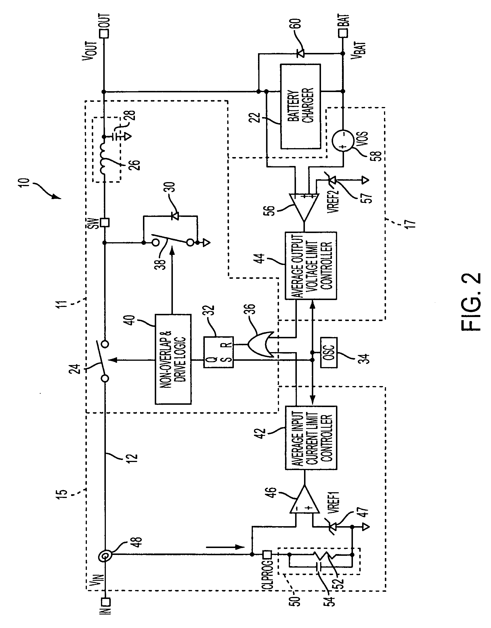
[0015]FIG. 2 illustrates one embodiment of a power manager for battery-powered applications. The power manager explained herein can provide efficient use of available input power under all load and battery conditions, and reduction in power dissipation of a battery charger. Power manger 10 may be, but is not necessarily, formed on a single chip.

[0016] A power manager 10 in FIG. 2 may include a circuit path 12 having an IN pin and an OUT pin. A wall adaptor or a source whose current is to be constrained such as a USB may be connected to the IN pin, and a load is tied to the OUT pin. A BAT pin, to which a battery is connected, is coupled to circuit path 12 through a battery charger 22. In this topology, the load is directly tied to circuit path 12, whereas the battery is not directly tied to the path.

[0017] Power manager 10 may be configured to drive the load from an available source of power, and simultaneously charge the battery with any available leftover current from the source....


PUM


Abstract

A power manager is configured to manage power for a battery-powered application. A power source, a load and a battery are interconnected through a circuit path. Power from the power source is provided to the load and battery by a switching regulator. Various implementations are presented.

Description

TECHNICAL FIELD [0001] This disclosure is related generally to a power manager and power managing method for a battery-powered application. Specifically, the disclosure relates to a power manager and method controlling power delivery to a load and a battery from a power source. Description of Related Art [0002] Rechargeable batteries are commonly used to power portable electronic devices, such as laptop computers, PDAs, digital cameras and MP3 players. Many of those portable electronic devices include circuitry for charging the batteries of the devices whenever the devices are connected to external power sources such as a wall adapter, USB, Firewire, and Ethernet. For example, the USB itself can be used to directly power the devices and charge the batteries. According to USB specifications, USB hosts or USB powered hubs are only allowed to provide as much as 500 mA from their nominal 5V supply. Therefore, the current drawn from the USB must be limited (regulated) by the portable ele...

Claims


Application Information

Patent Timeline
IPC IPC(8): H02J7/00
CPCH02J7/0068Y02E60/10G01R19/16542H01M10/44H02J7/00712
Inventor MARTIN, STEVENBARCELO, TREVORNORK, SAMUELZEMKE, ROGERSIMMONS, DAVID
Owner ANALOG DEVICES INT UNLTD
Why Eureka
Try Eureka