Liquid crystal display apparatus

a display apparatus and liquid crystal technology, applied in the field of liquid crystal display apparatus, can solve the problems of easy production of non-uniform brightness in the display image, increase in manufacturing costs, etc., and achieve the effect of increasing the number of components and manufacturing steps, and low cos

Active Publication Date: 2007-02-08
NEC LCD TECH CORP
View PDF3 Cites 11 Cited by
  • Summary
  • Abstract
  • Description
  • Claims
  • Application Information

AI Technical Summary

Benefits of technology

[0013] In accordance with the present invention, a light source is fixed to the touch panel. Therefore, the position of the light source does not vary when pressure is applied from

Problems solved by technology

However, the prior art described above has the following problems.
For this reason, in a conventional liquid crystal display apparatus 100 that has a touch panel and is configured in the manner shown in FIG. 1, the backlight I/F FPC substrate 106 on which the LEDs 104 are mounted is easily deformed by pressure applied by the touch pen when information is input, and there is a p

Method used


Image

  • Liquid crystal display apparatus
  • Liquid crystal display apparatus
  • Liquid crystal display apparatus

Examples


first embodiment

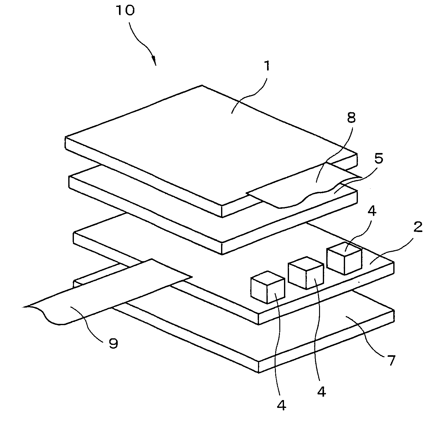
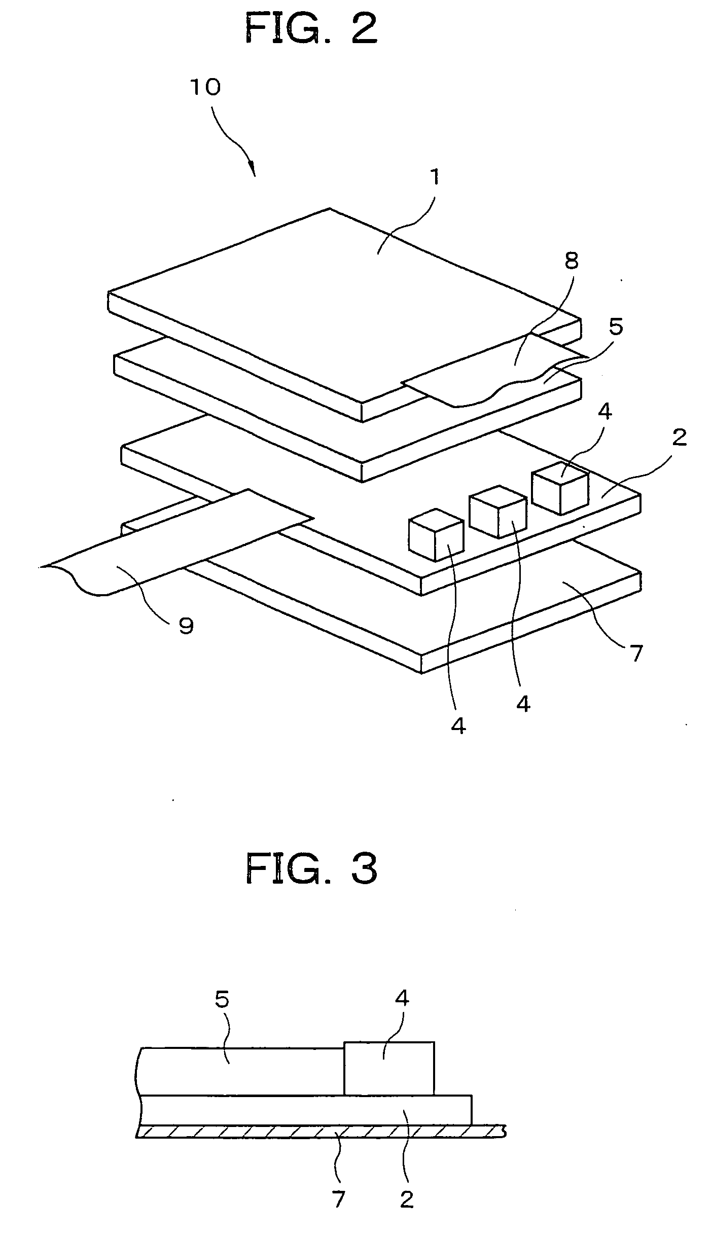
[0020] The liquid crystal display apparatus according to embodiments of the present invention is described in detail below with reference to the attached diagrams. Described first is the liquid crystal display apparatus of the present invention. FIG. 2 is an exploded perspective view of the liquid crystal display apparatus of the present embodiment, and FIG. 3 is a cross-sectional view of the arrangement of LEDs 4 in the liquid crystal display apparatus shown in FIG. 2. A liquid crystal panel 1 has been omitted in FIG. 3. The liquid crystal display apparatus 10 of the present embodiment is a liquid crystal display having a touch panel. An electromagnetic induction touch panel 2, a backlight light guide plate 5, and a liquid crystal panel 1 are disposed in the stated order on a shield plate 7 for protecting the apparatus against the effect of electromagnetic noise, as shown in FIG. 2.

[0021] The touch panel 2 in the liquid crystal display apparatus 10 has, for example, coiled wirings ...

second embodiment

[0029] Specifically, in the liquid crystal display apparatus 30 of the present embodiment, a backlight light guide plate 5 and a liquid crystal panel 1 are disposed in the stated order on the electromagnetic induction touch panel 2, and LEDs 4 used for the light source are mounted on the surface of touch panel 2 on the side that faces the light guide plate 5 along the end face of the light guide plate 5. Connected to the touch panel 2 are an backlight I / F FPC substrate 6 for feeding power to the LEDs 4, and a touch-panel I / F FPC substrate 3 for feeding power and signals to the touch panel 2. A liquid crystal panel I / F FPC substrate 8 for feeding power to the liquid crystal panel 1 is connected to the liquid crystal panel 1. Except for the above-described differences in the liquid crystal display apparatus 30 of the present embodiment, the structure and operation are the same as the liquid crystal display apparatus of the second embodiment described above.

[0030] In the liquid crystal...


PUM


Abstract

A plurality of LEDS used for a light source are mounted on the surface of an electromagnetic-induction touch panel in which coiled wiring is formed on a glass epoxy substrate. A dual-use touch-panel/backlight I/F FPC substrate is connected to the touch panel in order to feed power to the LEDs and to feed power and signals to the touch panel. A shield plate 7 is disposed on the reverse side of the touch panel, and a backlight light guide plate and a liquid crystal panel are disposed in the stated order on the side on which the LEDs are mounted. A liquid crystal panel I/F FPC substrate for feeding power to the liquid crystal panel is connected to the liquid crystal panel.

Description

BACKGROUND OF THE INVENTION [0001] 1. Field of the Invention [0002] The present invention relates to a liquid crystal display apparatus provided with an electromagnetic-induction touch panel, and more particularly relates to a liquid crystal display apparatus incorporated in a mobile information terminal apparatus, a tablet personal computer, or another information processing apparatus. [0003] 2. Description of the Related Art [0004] Display apparatuses having a touch panel are provided with both image display and information input functions, and are currently widely used in ATMs (automated teller machines) for financial institutions and in other equipment. In particular, electromagnetic-induction touch panels that detect electromagnetic energy generated in the panel by a dedicated pen can be operated only with this pen, even when the pen does not make direct contact with the panel. The panel can therefore be disposed further rearward from the liquid crystal panel. For this reason, ...

Claims


Application Information

Patent Timeline
IPC IPC(8): G09G3/36
CPCG02B6/0068G02B6/0081G06F3/046G02F1/133615G06F3/0412G02F1/13338
Inventor ITO, YUKIHIRO
Owner NEC LCD TECH CORP
Why Eureka
Try Eureka