
Tapered roller bearing device for wheel

Inactive Publication Date: 2007-02-08
NTN CORP
View PDF7 Cites 25 Cited by
  • Summary
  • Abstract
  • Description
  • Claims
  • Application Information

AI Technical Summary

Benefits of technology

[0005] The present invention is intended to provide a tapered roller bearing assembly for supporting a vehicle wheel, in which stress concentration tending to occur in the vicinity of the large collar adjacent a flange in the hub axle is lessened to increase the durability of the bearing assembly.
[0007] According to the present invention, the collar provided in the vicinity of the rolling face adjacent the hub flange of the hub axle is formed as a collar ring separated from the hub axle and this separate collar ring is mounted externally on the hub axle. Therefore, stress concentration, tending to occur due to the load imposed by the tapered rollers at a boundary between the rolling face of the hub axle and a surface of the collar, can be lessened. Thus, even though the bearing assembly of the present invention is used in association with a kind of vehicles having a heavy weight, the fatigue hardly occurs in the boundary referred to above, rendering the bearing assembly of the present invention robust.
[0009] In the case of this construction, since the arcuately sectioned surface area lying from the collar ring mounted area to the side face of the hub flange has a large radius of curvature, the stress concentration loaded on that portion through the tapered rollers can further be lessened.
[0011] In the case of this construction, in spite of the use of the separate collar ring, the outboard sealing member between the outer member and the inner member can be arranged with high space efficiency. For this reason, it is possible to use the collar ring of a sufficient size for given bearing dimensions to achieve excellent durability and, also, the sealability can be secured.
[0013] In the case of this construction, since the hub axle has no collar that continues to the rolling face on the outboard side, the outer peripheral surface of the hub axle can have a shape smoothly continuing from the rolling face on the outboard side towards the hub flange, with the stress concentration lessened consequently. For this reason, there is no increase of the fatigue resulting from the stress concentration and the wheel support bearing assembly excellent in durability can be obtained. Though the outer member is provided with the collar, a problem associated with the stress concentration is minimal since the outer member 11 is on a fixed side.

Problems solved by technology

For this reason, a fatigue is apt to occur in a portion of the bearing assembly adjacent the machining recess 22c, making it difficult to improve the durability.

Method used


Image

  • Tapered roller bearing device for wheel
  • Tapered roller bearing device for wheel
  • Tapered roller bearing device for wheel

Examples


Embodiment Construction

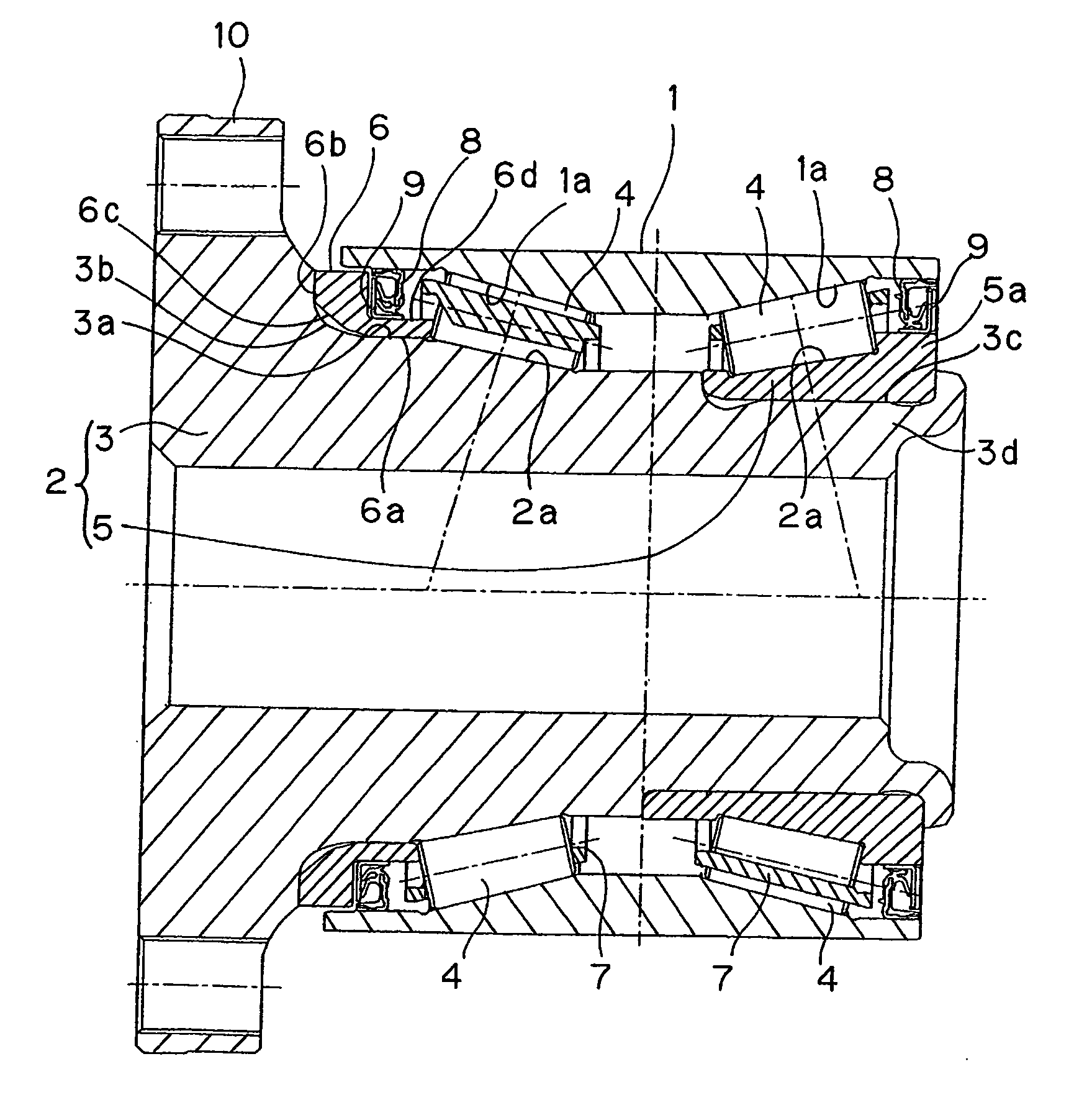
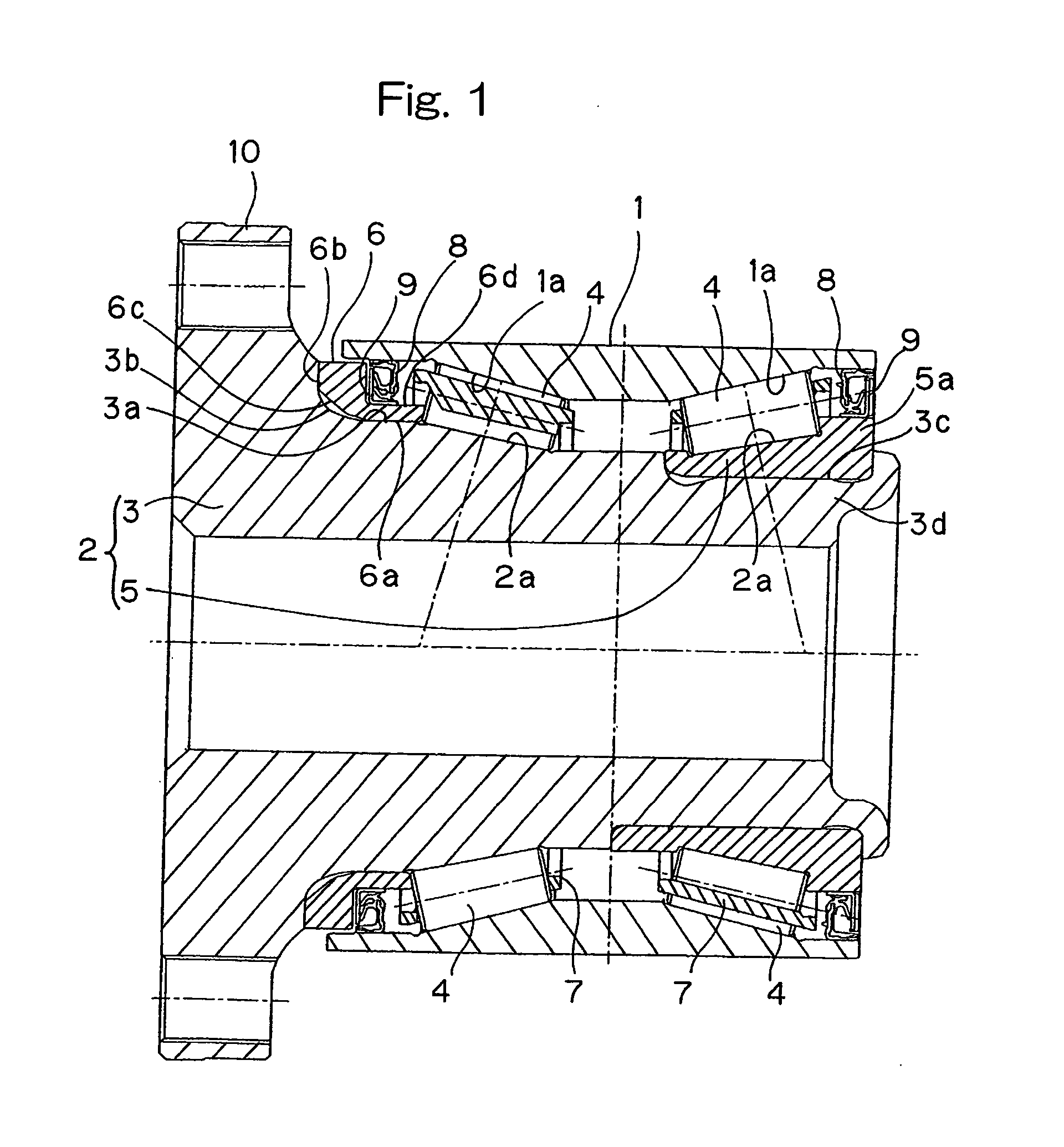
[0017] Referring to FIG. 1 showing a first preferred embodiment of the present invention, a tapered roller bearing assembly for supporting a vehicle wheel shown therein is a dual row tapered bearing model of a hub unit type. This wheel support bearing assembly includes an outer member 1 having an inner periphery formed with dual rows of tapered rolling faces 1a, in which reduced diameter ends adjoin with each other, an inner member 2 having an outer periphery formed with tapered rolling faces 2a confronting the rolling faces 1a, and dual rows of tapered rollers 4 interposed between the rolling faces 1a in the outer member 1 and the rolling faces 2a in the inner member 2. The tapered rollers 4 are retained by a roller retainer 7 employed for each of the rows of the tapered rollers 4. The outer member 1 is provided at its opposite ends with sealing members 8, respectively, for sealing an annular space delimited between the inner and outer members 2 and 1.

[0018] The inner member 2 is ...


PUM


Abstract

To provide a tapered roller bearing assembly for supporting a vehicle wheel, in which stress concentration in the vicinity of a collar adjacent a hub flange is lessened to improve the durability, the assembly includes an outer member (1) having a plurality of tapered rolling faces (1a), an inner member (2) having a corresponding number of tapered rolling faces (2a), a corresponding number of rows of tapered rollers (4). The inner member (2) includes a hub axle (3) with a hub flange (10) adjacent an outboard end, and a single row inner race (5) mounted externally on an inboard end of the hub axle (3). The rolling faces (2a) are formed on the hub axle (3) and the single row inner race (5). A collar ring (6) in contact with the large ends of the tapered rollers (4) of the outboard row is provided as a flange ring (6) separate from the hub axle (3) and fitted on the hub axle (3) at a position adjacent the hub flange (10).

Description

FIELD OF THE INVENTION [0001] The present invention generally relates to a tapered roller bearing assembly of a hub unit type for rotatably supporting a vehicle wheel and, more particularly, to the wheel support bearing assembly for use in full-size trucks, station wagons and estate cars. BACKGROUND ART [0002] As a wheel support bearing assembly, a hub unit type tapered roller bearing assembly (of a third generation model) such as shown in FIG. 3 of the accompanying drawings has hitherto been known. The bearing assembly shown in FIG. 3 includes a plurality of circumferentially extending rows of tapered rollers 24 interposed between an outer member 21 and an inner member 22, in which the inner member 22 is comprised of a hub axle 23 and an inner race 25 for one of the circumferential rows of the tapered rollers 24. The hub axle 23 and the inner race 25 has rolling faces 22a defined therein for those circumferential rows of the tapered rollers 24. The hub axle 23 is formed with a larg...

Claims


Application Information

Patent Timeline
IPC IPC(8): F16C33/58F16C13/00F16C35/00B60B27/00F16C19/38F16C33/60
CPCB60B27/00F16C33/605F16C19/386B60B27/001F16C33/7813F16C2326/02F16C33/581
Inventor KOMORI, KAZUOIMOU, AKITOSHI
Owner NTN CORP
Learn More