
Computer cooling fan

a cooling fan and computer technology, applied in the field of cooling fans, can solve the problems of insufficient cooling of computer components, insufficient heat dissipation and cooling properties of fans, and physical discomfort of users, so as to reduce the level of emitted noise and increase air flow

Inactive Publication Date: 2007-02-08
KIM JINSEOK
View PDF5 Cites 9 Cited by
  • Summary
  • Abstract
  • Description
  • Claims
  • Application Information

AI Technical Summary

Benefits of technology

[0008] One objective of the present invention is to provide an increased air flow over electronic components as compared to the related art cooling fans. Another objective of the present invention is to reduce the level of emitted noise when the air flow over the electronic components is of a similar level as that of the related art cooling fan.

Problems solved by technology

Other related art cooling fans that are known as radial blowers provide air flow in a lateral manner which may not adequately lower the temperature of computer components to prevent component degradation or failure.
Related art cooling fans do not provide adequate heat dissipation and cooling properties for these advanced computer architectures.
For example, a laptop computer with a GHz processor, having a related art cooling fan, may reach operating temperatures causing a user physical discomfort.
The physical discomfort may include tingling of a user's skin, or in extreme cases, burning of a user's skin in close proximity to the laptop computer by hot electronic components.
However, the increased rotation speed causes an increase in a level of emitted noise in comparison to emitted noise at a slower rotation speed.
This increase in the level of emitted noise may disturb a user in close proximately to the related art cooling fan.

Method used


Image

  • Computer cooling fan
  • Computer cooling fan
  • Computer cooling fan

Examples


Embodiment Construction

[0019] The present invention relates to cooling fans. More particularly, the invention relates to a cooling fan to cool electronic components in a computer.

[0020] Although the invention is illustrated with respect to a cooling fan for a computer, it is contemplated that the invention may be utilized wherever there is a desire for efficiently cooling electronic components that generate heat. Reference will now be made in detail to the preferred embodiments of the present invention, examples of which are illustrated in the accompanying drawings.

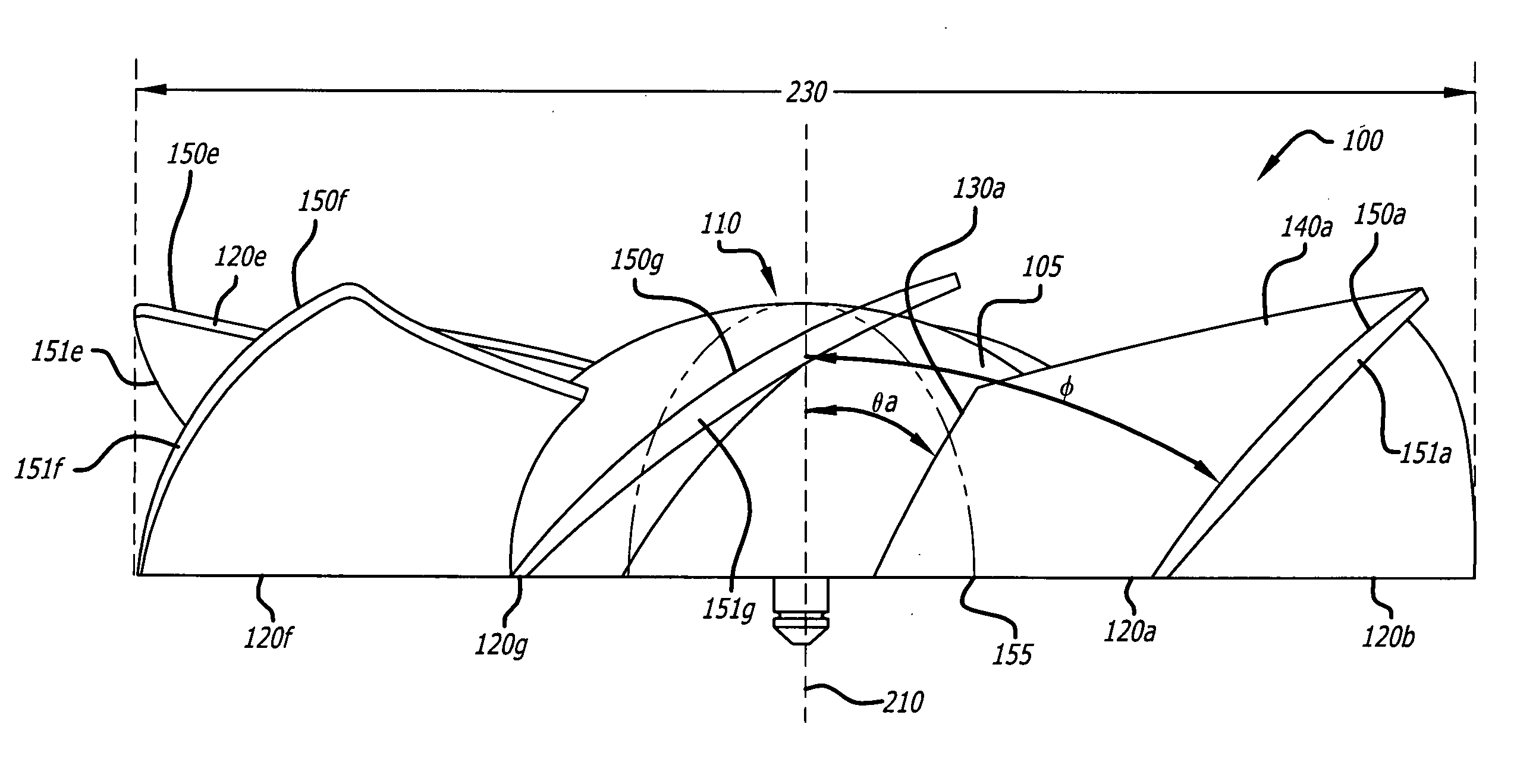
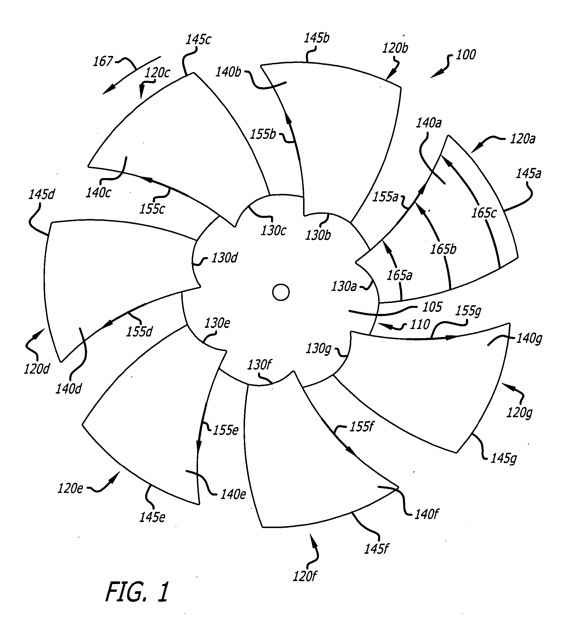
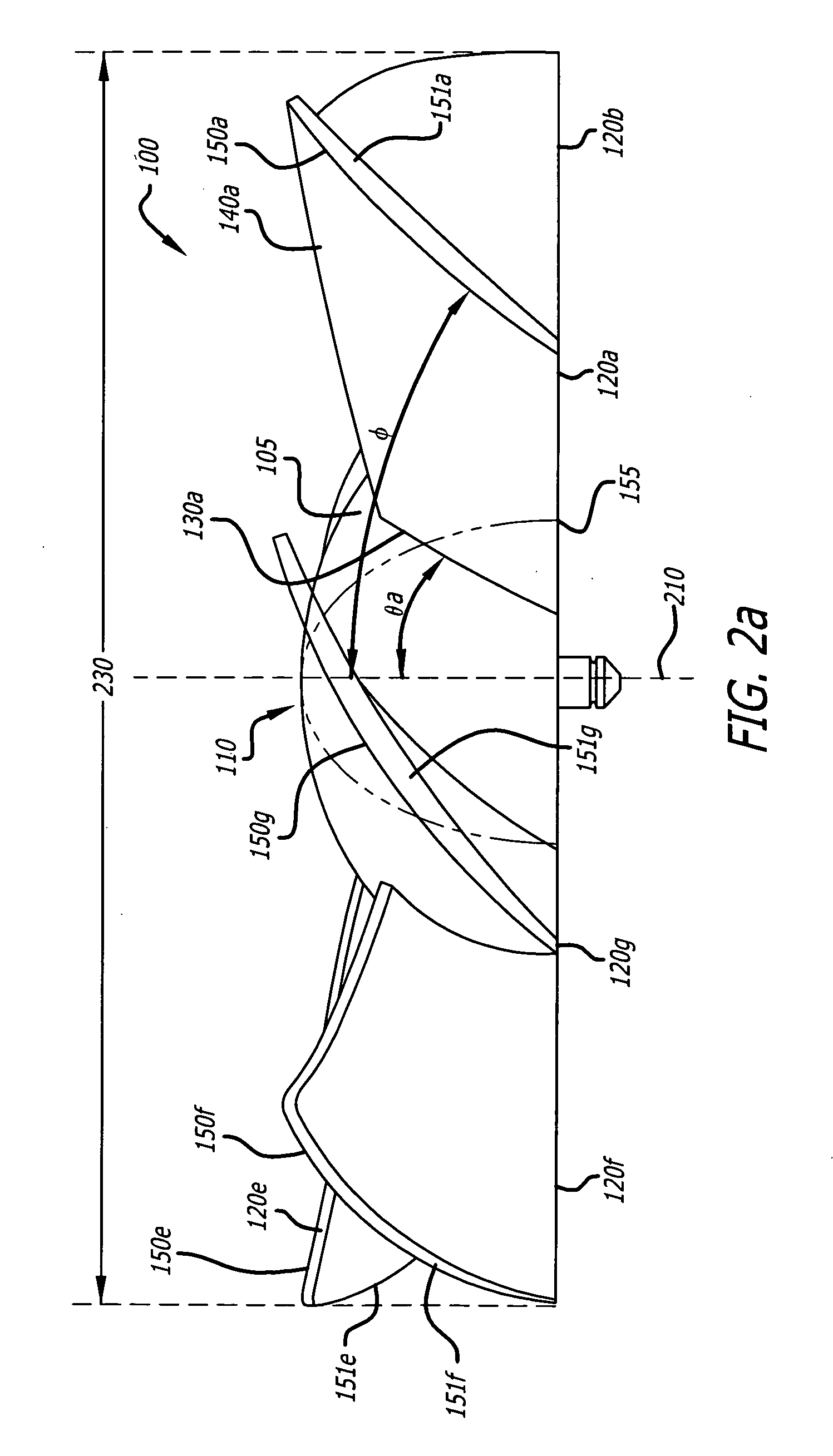
[0021]FIGS. 1, 2a, 2b, 2c and 3 illustrate a front profile view, a side view, a partial perspective side view and a partial section view of a cooling apparatus, respectively, in accordance with one embodiment of the present invention.

[0022] As shown, a cooling apparatus 100 is disclosed to increase airflow over electronic components 300a-c (see FIG. 3). A non-flat hub 110 is disposed substantially centered about an axis of rotation 210. The ...


PUM


Abstract

A cooling apparatus to increase airflow over electronic components is disclosed. The cooling apparatus comprises a non-flat hub disposed substantially centered about an axis of rotation. A plurality of fan blades, each of the plurality of fan blades is connected at a first end to an outer shell of the non-flat hub to form a first intersection angle greater than approximately 10 degrees between a top surface of the first end and the axis of rotation. Each of the plurality of fan blades has a substantially convex shaped outer surface to sweep air substantially parallel to the axis of rotation for passage through an effective channel surface area formed by an outer surface of the non-flat hub and a top surface of the plurality of fan blades.

Description

FIELD OF THE INVENTION [0001] The present invention relates to cooling fans. More particularly, the invention relates to a cooling fan to cool electronic components in a computer. BACKGROUND OF THE INVENTION [0002] There are cooling fans commercially available to reduce heating of electronic components within confined environments, such as within an interior volume of a computer. These cooling fans are made from materials such as plastic or light metals including aluminum or steel. For example, there are related art cooling fans that have a central hub with diagonally attached blades that rotate within a cylindrical chamber to force air through the cylindrical chamber. Other related art cooling fans that are known as radial blowers provide air flow in a lateral manner which may not adequately lower the temperature of computer components to prevent component degradation or failure. [0003] In light of recent advances in computer architecture, there is a need for cooling fans to increa...

Claims


Application Information

Patent Timeline
IPC IPC(8): F04D29/38
CPCF04D29/384F04D29/329
Inventor KIM, JINSEOK
Owner KIM JINSEOK
Learn More