Chain guide device

a technology of chain guide and guide rod, which is applied in the direction of guards, cycle equipment, gear, etc., can solve the problems of increasing the number of parts and increasing the weight, and achieve the effects of improving the service life of the plate member, increasing height, and improving the mounting workability of the chain guide member

Inactive Publication Date: 2007-02-08
HONDA MOTOR CO LTD
View PDF5 Cites 29 Cited by
  • Summary
  • Abstract
  • Description
  • Claims
  • Application Information

AI Technical Summary

Benefits of technology

[0020] As a result, the mounting workability for the chain guide member is improved.
[0021] The first stopper portion is provided by the flange portion formed at the front end of the chain guide member, with the flange portion in contact with the front end portion of the plate member. Accordingly, direct contact of the chain and the plate member can be reduced.
[0022] Since direct contact of the chain and the plate member can be reduced as mentioned above, the service life of the plate member can be extended.
[0023] The second stopper portion is provided by the ridge portion formed at the upper portion of the chain guide member so as to increase in height toward the rear end thereof, with the ridge portion

Problems solved by technology

This results in an increase in number of

Method used


Image

  • Chain guide device
  • Chain guide device
  • Chain guide device

Examples


Embodiment Construction

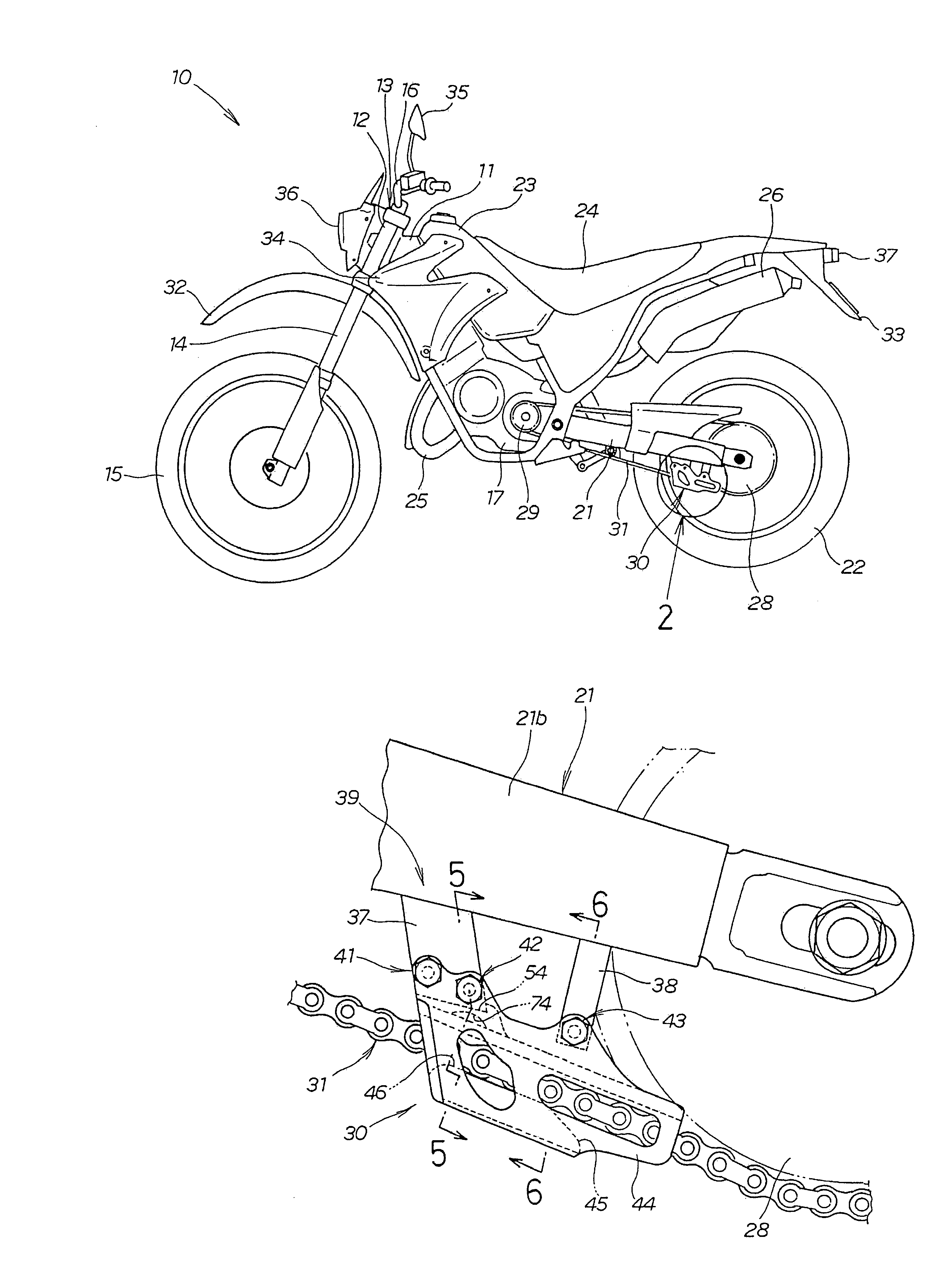
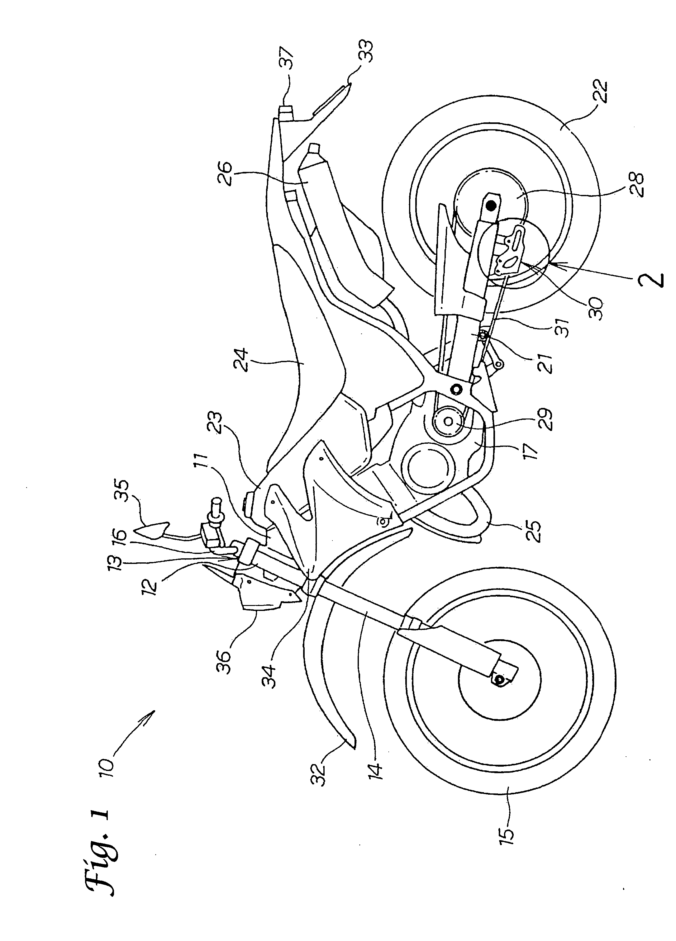
[0033] An embodiment of the present invention will now be described with reference to the attached drawings. Each drawing is to be viewed in the same direction as that of reference numerals included therein. FIG. 1 is a side view of a motorcycle 10 according to the present invention. The motorcycle 10 includes a main frame 11, a head pipe 12 mounted to the front end of the main frame 11, a steering frame 13 steerably mounted to the head pipe 12, a front fork 14 mounted to a lower portion of the steering frame 13, a front wheel 15 rotatably mounted to a lower end portion of the front fork 14, a steering handle 16 mounted to an upper portion of the steering frame 13 for steering the front wheel 15, an engine 17 mounted to the main frame 11, a rear swing arm 21 vertically swingably mounted to the main frame 11, a rear wheel 22 rotatably mounted to a rear end portion of the rear swing arm 21, a fuel tank 23 mounted to an upper portion of the main frame 11, a rider seat 24 mounted to the...


PUM


Abstract

A chain guide device which can be easily mounted with a reduced number of parts. The chain guide device for guiding a chain in a vehicle includes a main frame and a rear swing arm extending rearward from the main frame. The chain guide device also includes a stay extending downward from the rear swing arm, a sectionally U-shaped plate member fastened to the stay using fastening members, and a chain guide member mounted in the plate member. The chain guide member has a chain guide hole through which the chain passes through to be guided. The chain guide member is fixed by fitting the lower surface and the right and left side surfaces of the chain guide member to the plate member and by fitting the upper surface of the chain guide member to the stay.

Description

FIELD [0001] The present invention relates to a chain guide device provided on a rear swing arm for guiding a chain wrapped between a drive sprocket mounted to an engine and a rear sprocket mounted to a rear wheel. BACKGROUND [0002] Conventionally, a chain guide device is provided on a rear swing arm for guiding a chain wrapped between a drive sprocket mounted to an engine and a rear sprocket mounted to a rear wheel. The chain guide device includes a guide plate member formed of metal and a chain guide member formed of resin, whereby the chain guide member is surrounded and held by the guide plate member. [0003] FIG. 4 of published patent application Japanese Utility Model Laid-open No. 3-5588 discloses a sectional view of a chain guide device 18 (reference numerals cited herein are those shown in the above mentioned publication). This chain guide device 18 includes a stay 41 with a forked shape and a lower opening provided on a rear fork 9, a sectionally U-shaped chain guide plate ...

Claims


Application Information

Patent Timeline
IPC IPC(8): B62J13/00F16H57/02F16H7/18F16H7/08F16D1/00B62J13/04
CPCB62M9/16F16H7/18B62M2009/007
Inventor UCHIYAMA, MIKIOGOGO, KAZUHIKO
Owner HONDA MOTOR CO LTD
Why Eureka
Try Eureka