

Angular position adjusting mechanism
a technology of adjusting mechanism and angle, which is applied in the direction of gearing, hoisting equipment, chairs, etc., can solve the problems of large load liable to act on the gear, disadvantageous background art in ensuring meshing strength, etc., and achieves the effect of small backlash, large backlash, and high meshing strength of the gears
- Summary
- Abstract
- Description
- Claims
- Application Information
AI Technical Summary
Benefits of technology
Problems solved by technology
Method used
Image

Examples
Embodiment Construction
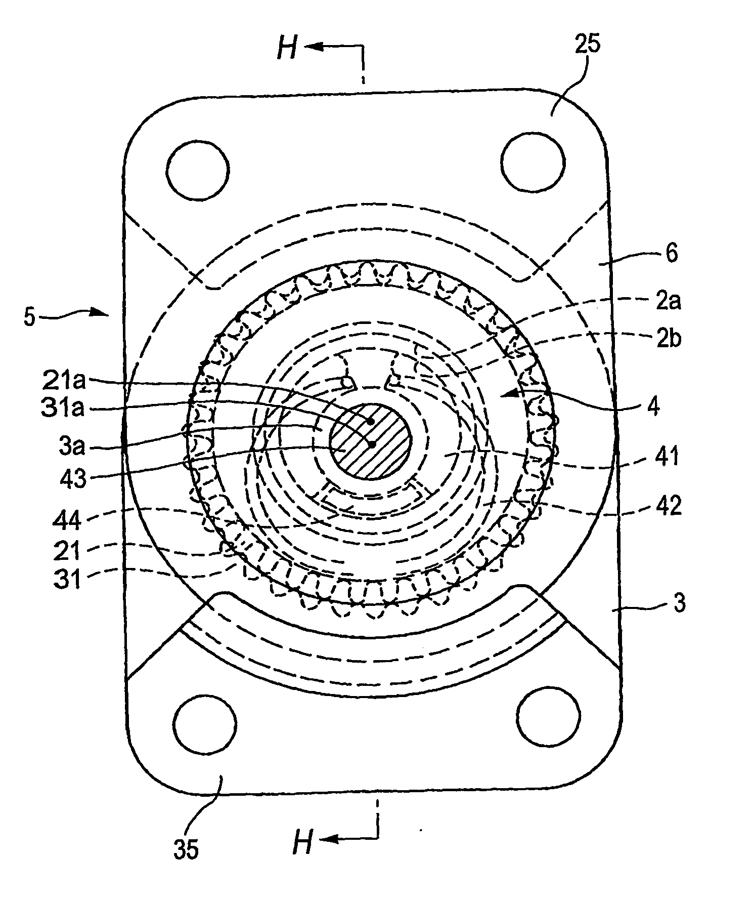
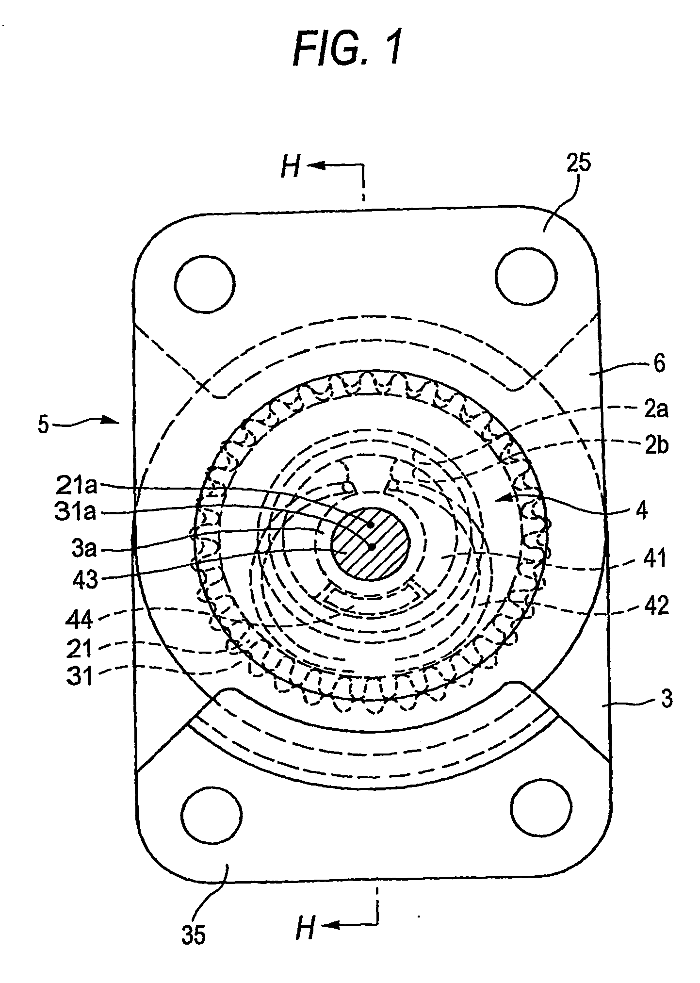
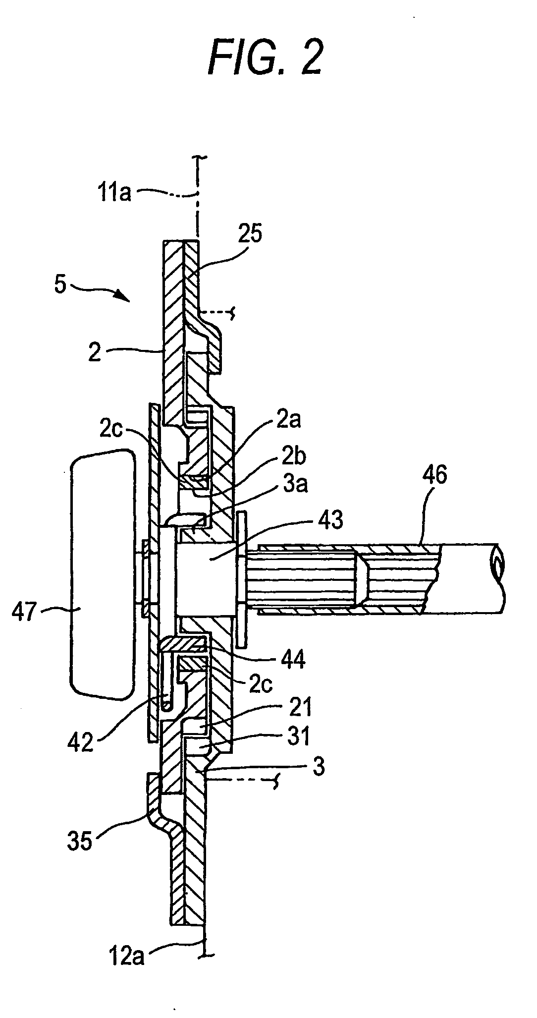
[0036] Hereinafter, an angular position adjusting mechanism 5, which is a first embodiment of the invention, is described with reference to FIGS. 1-4, and 6.
[0037] Referring to FIG. 6, the angular position adjusting mechanism 5 is applicable to, for example, a reclining apparatus 50 for adjusting a reclining angle of a seat back 11 of a vehicular seat 10, or to a vertical apparatus 60 for adjusting a height of a seat cushion 12 thereof. That is, the reclining apparatus 50 is configured so that the angular position adjusting mechanism 5 is mounted between a frame 11a of the seat back 11 and a frame 12a of the seat cushion 12, and that an angle of inclination of the seat back 11 can arbitrarily be adjusted by rotating an operating handle 47. When the operating handle 47 is not operated, predetermined strength is ensured so as to hold the position of the seat back 11. Thus, an occupant can be supported. Similarly, the vertical apparatus 60 is configured so that the angular position ad...
PUM
 Abstract
Description
Claims
Application Information