Method of using a PTO clutch for auxiliary load measurement

Active Publication Date: 2007-02-08
DEERE & CO
View PDF2 Cites 12 Cited by
  • Summary
  • Abstract
  • Description
  • Claims
  • Application Information

AI Technical Summary

Benefits of technology

[0011] In general, when an auxiliary device is being powered by the PTO driveline the PTO clutch is periodically slowly ramped down in pressure until slippage is detected in the clutch. Slippage is determined by monitoring the shaft speed into the clutch as well as the shaft speed downstream of the clutch. By determining the commanded pressure where slippage occurred, the equivalent engine power that is going to the auxiliary function is calculated. With this information, the proportion of the engine load signal that is going to the auxiliary

Problems solved by technology

A problem that may occur is that the engine load signal may be misleading.
This may cause problems where the shift quality is harsh because the oncoming clutch pressure is commanded at high pressure when instead it should have been commanded low because there was actually only a small amount of the engine power that was going to the drive wheels.
If the tractor slows down excessively during a shift, it is an indication that the assumption of engine load that is going to the wheels is too low.
If the tractor speeds up during a shift, it is an indication that t

Method used


Image

  • Method of using a PTO clutch for auxiliary load measurement
  • Method of using a PTO clutch for auxiliary load measurement
  • Method of using a PTO clutch for auxiliary load measurement

Examples


Example

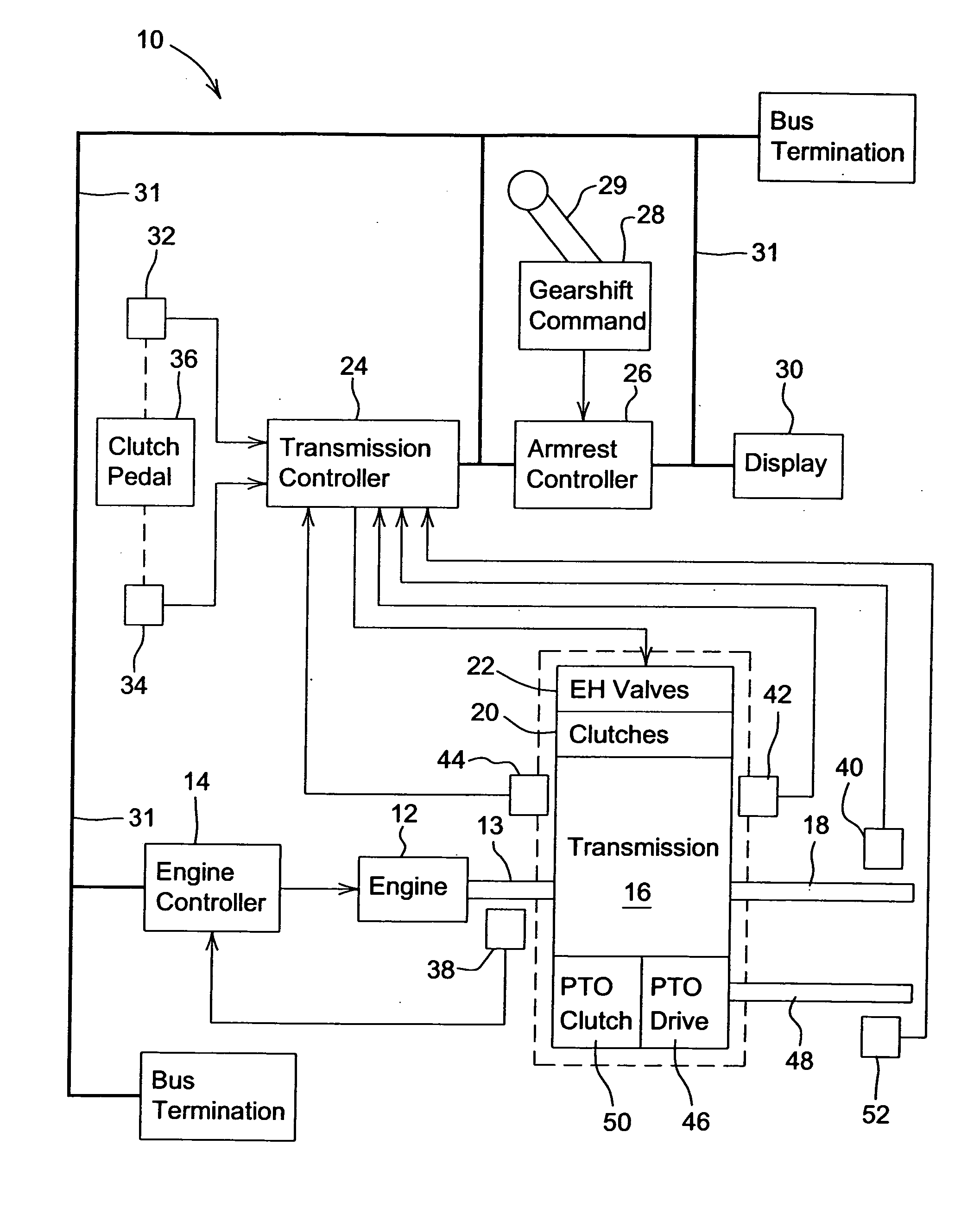
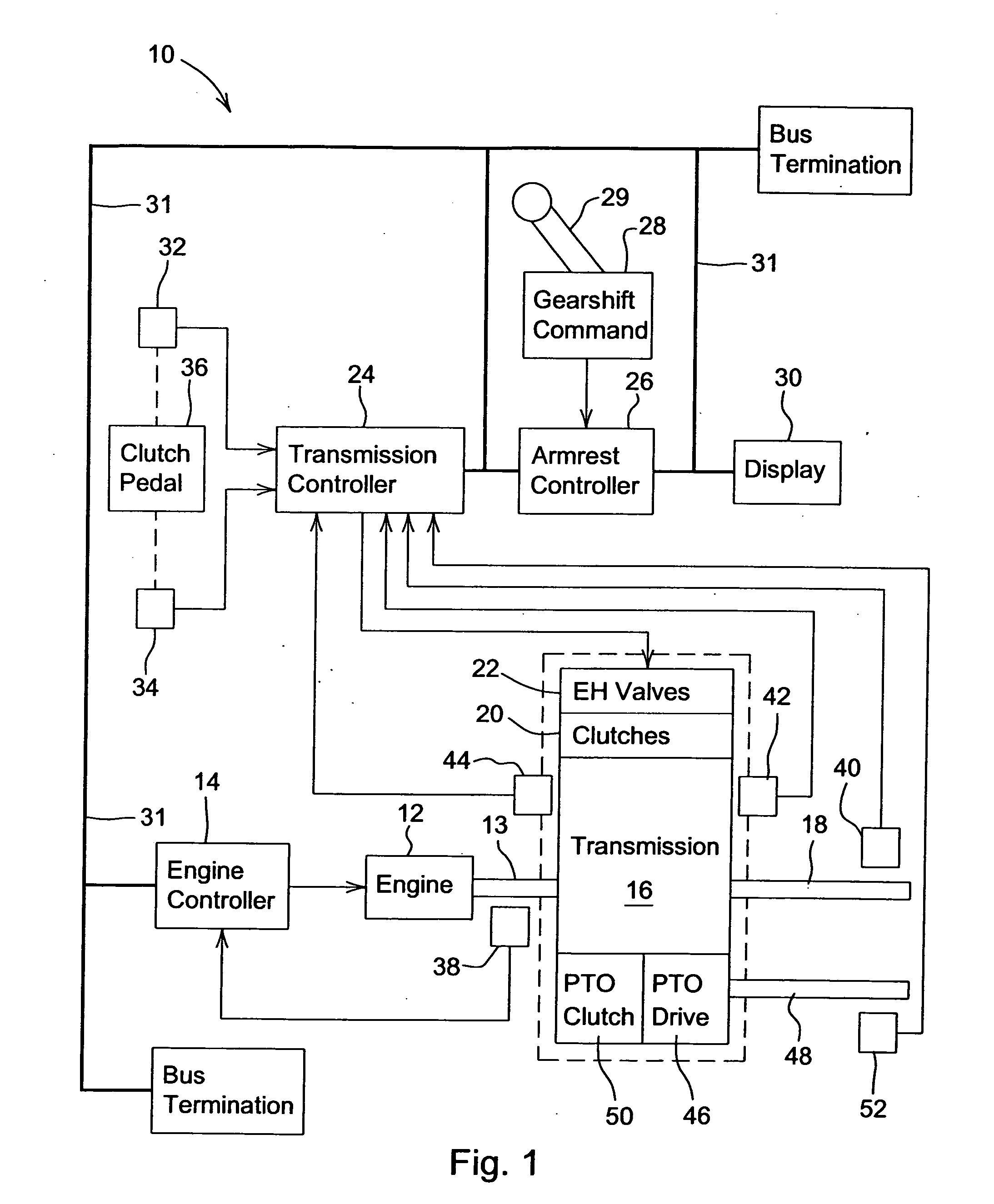
[0018] With reference now to the drawings, and more particularly to FIG. 1, it can be seen that a microprocessor-based transmission control system to which the present invention is applicable is designated generally by the numeral 10. A vehicle power train includes an engine 12 which is controlled by electronic engine control unit 14, and which drives a power shift transmission (PST) 16 via input shaft 13. Transmission 16 has an internal countershaft (not shown), and an output shaft 18 which is connected to drive wheels (not shown). The PST 16 includes a set of pressure operated control elements or clutches 20 which are controlled by a corresponding set of solenoid operated proportional control valves 22. The transmission 16 may be a transmission such as described in U.S. Pat. No. 5,011,465, issued Apr. 30, 1991 to Jeffries et al., and assigned to the assignee of this application. The valves 22 may be two-stage electro-hydraulic valves as described in U.S. Pat. No.4,741,364, issued ...


PUM


Abstract

A method is provided wherein when an auxiliary device is being powered by the PTO driveline the PTO clutch is periodically slowly ramped down in pressure until slippage is detected in the clutch. Slippage is determined by monitoring the shaft speed into the clutch as well as the shaft speed downstream of the clutch. By determining the commanded pressure where slippage occurred, the equivalent engine power that is going to the auxiliary function is calculated. With this information, the proportion of the engine load signal that is going to the auxiliary function versus the drive wheels is determined. After slip is detected in the PTO clutch, pressure is ramped back up in the clutch so as to minimize the amount of slippage.

Description

FIELD OF THE INVENTION [0001] The present invention relates generally to vehicle transmissions. More particularly, the present invention relates to transmissions for work vehicles having a Power-Take-Off (PTO). Specifically, the present invention relates to a method of using a PTO clutch for measurement of auxiliary loads. BACKGROUND OF THE INVENTION [0002] Conventionally, when shifting gears, many powershift transmissions use solenoid controlled valves to control pressure to each clutch and rely on a signal that is representative of engine load to determine the pressure applied to the on-coming clutches. [0003] A problem that may occur is that the engine load signal may be misleading. For example, in agricultural tractor applications, there are conditions where much of the engine load may be used to power auxiliary functions such as a hydraulic pump or PTO implements. This may cause problems where the shift quality is harsh because the oncoming clutch pressure is commanded at high ...

Claims


Application Information

Patent Timeline
IPC IPC(8): B60K41/04
CPCB60W10/06B60W10/30B60W30/1888Y10T477/688Y10T477/755Y10T477/675B60W2510/0241
Inventor MEYER, DUANEMASON, JOELALLEN, DANIELMERRILL, BRADLEY
Owner DEERE & CO
Why Eureka
Try Eureka