
System and method of computing the operating parameters of a forge welding machine

a forging welding machine and operating parameter technology, applied in welding/soldering/cutting articles, other domestic articles, manufacturing tools, etc., can solve the problems of high solid phase rate and short period of tim

Active Publication Date: 2007-02-15
THERMATOOL
View PDF31 Cites 9 Cited by
  • Summary
  • Abstract
  • Description
  • Claims
  • Application Information

AI Technical Summary

Benefits of technology

[0024] In one aspect the present invention is a system for controlling the parameters of a forge welding machine for the forge welding of one or more materials. The system comprises a computer, one or more computer memory storage devices and a compu

Problems solved by technology

At this temperature diffusion rates in the solid phase are very high and a quality bond results in a very short period of time.

Method used


Image

  • System and method of computing the operating parameters of a forge welding machine
  • System and method of computing the operating parameters of a forge welding machine
  • System and method of computing the operating parameters of a forge welding machine

Examples


Embodiment Construction

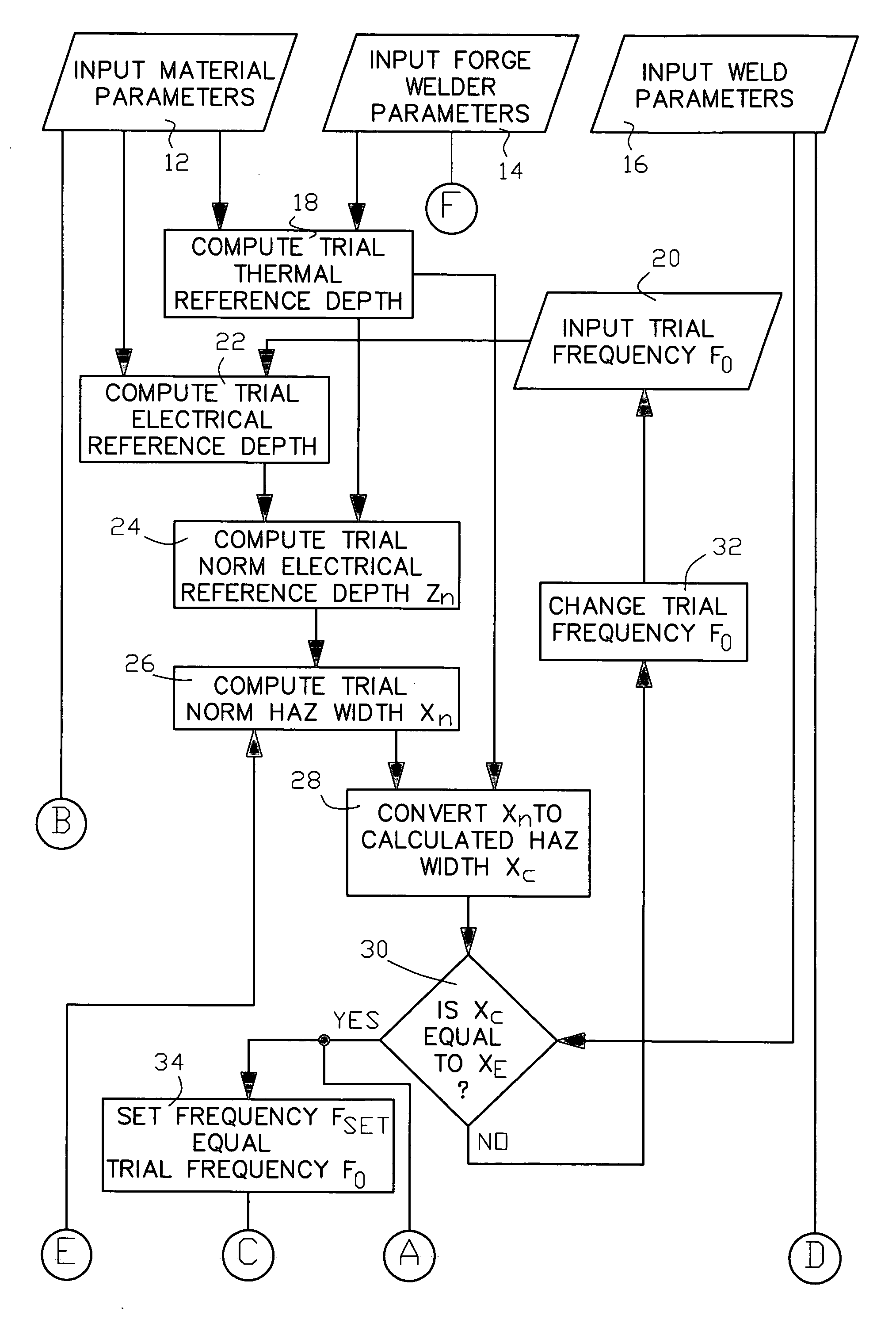
[0035] There is illustrated in FIG. 6(a) and FIG. 6(b) one non-limiting example of the system and method of computing the operating parameters of a forge welding machine of the present invention. Although the system and method are directed to the induction forge welding of the longitudinal edges of a metal strip or plate, with appropriate modifications, one skilled in the art may apply the system or method to any forge welding process in which a HAZ is created. The routines in the figures may be embodied in computer program code that is prepared by one skilled in the art and executed with suitable computer hardware, including but not limited to, processors, memory storage devices, and input and output devices. The term “metal” is used for simplicity to describe the material part or parts being forge welded together, including but not limited to metal strips and plates. The term “forge welder” or “forge welding machine” is used for simplicity to generally describe the machinery used ...


PUM

PropertyMeasurementUnit
Temperatureaaaaaaaaaa
Thicknessaaaaaaaaaa
Densityaaaaaaaaaa

Abstract

A system and method for computing the parameters of a forge welding machine for the forge welding of one or more materials is provided. A computer program executes a self-tuning routine to compute the operating frequency and operating power setting for the forge welding machine in response to an inputted width of the heat affected zone and an inputted weld temperature.

Description

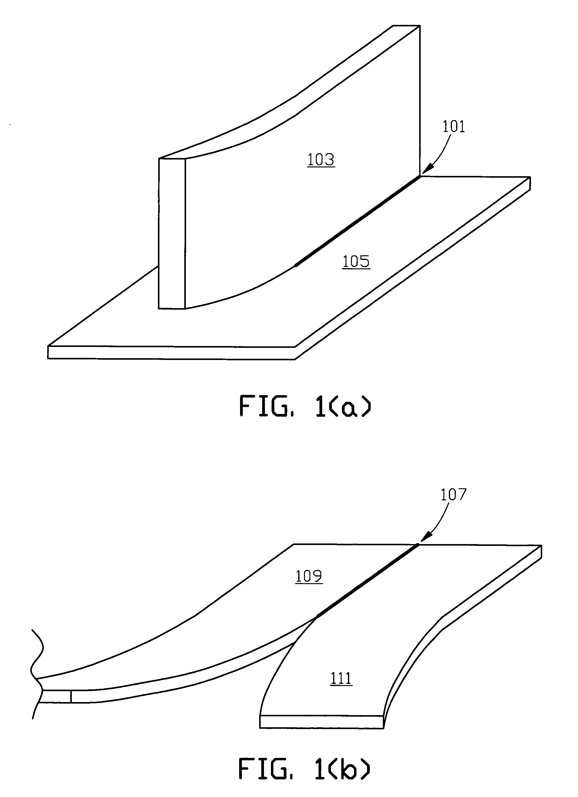
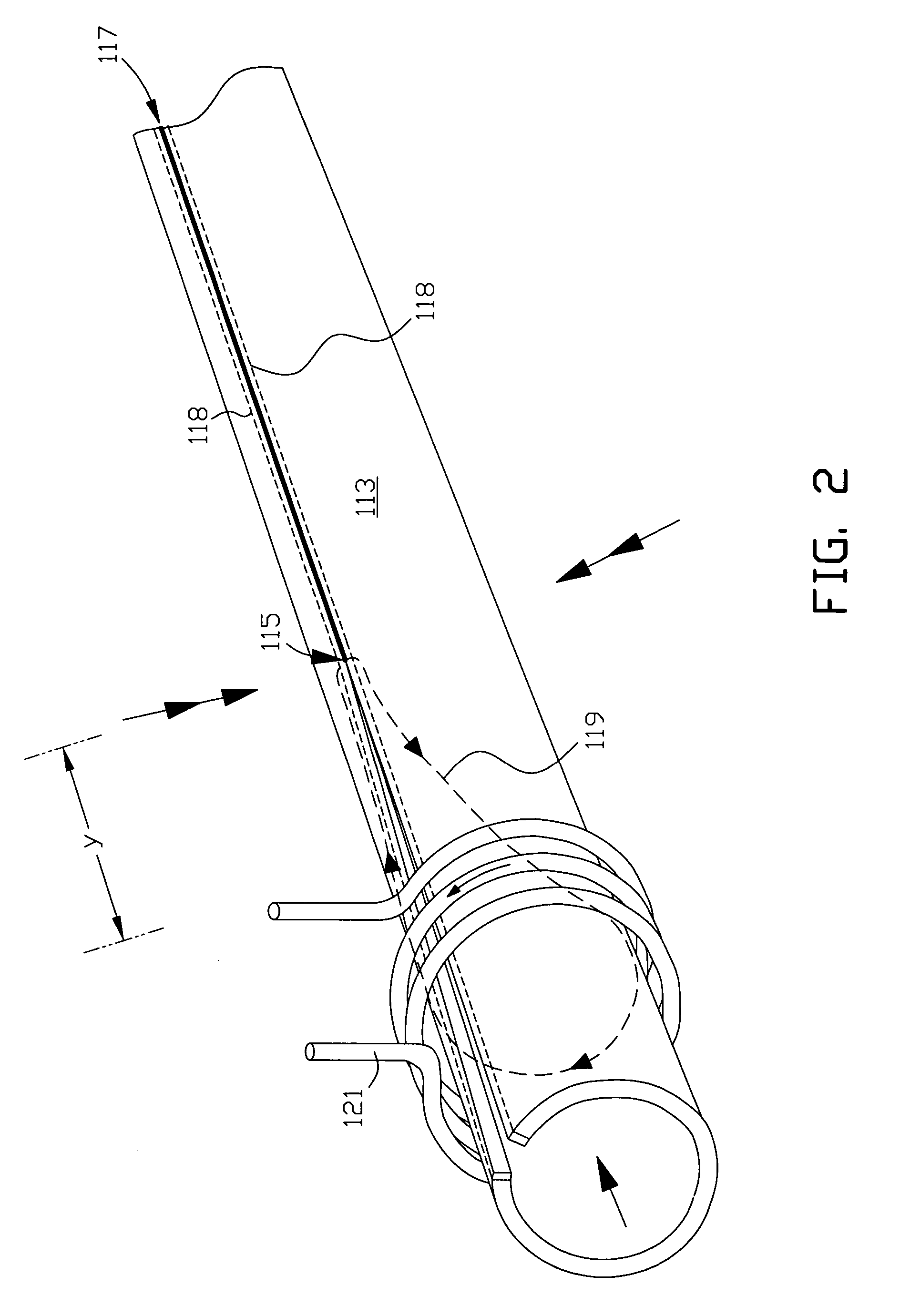
CROSS REFERENCE TO RELATED APPLICATIONS [0001] Not applicable. FIELD OF THE INVENTION [0002] The present invention generally relates to forge welding processes and in particular to controlling the parameters of a forge welding machine in response to an inputted width of the heat affected zone and weld temperature for the forge welding process. BACKGROUND OF THE INVENTION [0003] Forge welding includes the bonding together of metal parts, such as plates. For example FIG. 1(a) illustrates a typical partial T-joint forge weld 101 made between an edge of plate 103 and surface of plate 105, and FIG. 1(b) illustrates a typical square butt partial forge weld 107 made between facing edges of plates 109 and 111. Forge welding also includes the bonding together of edge portions of a folded metal sheet or strip wherein the edge portions are forced together at a weld point as the strip is longitudinally advanced in the direction of the formed weld seam. For example in FIG. 2, tube 113 is formed ...

Claims


Application Information

Patent Timeline
IPC IPC(8): B23K11/02
CPCB23K13/02B23K2201/18B23K2201/06B23K13/025B23K2101/06B23K2101/18
Inventor SCOTT, PAUL F.NALLEN, MICHAEL A.DOYON, GARY A.MORTIMER, JOHN H.FISHMAN, OLEG S.
Owner THERMATOOL
Learn More