Method for hybrid rasterization and raytracing with consistent programmable shading

a raytracing and hybrid technology, applied in the field of computer generated visualizations, can solve problems such as visible differences in color and brightness, and achieve the effect of consistent image, accurate evaluation and rendering reflections

Active Publication Date: 2007-02-15
DASSAULT SYST 3DEXCITE +1
View PDF7 Cites 58 Cited by
  • Summary
  • Abstract
  • Description
  • Claims
  • Application Information

AI Technical Summary

Benefits of technology

[0014] The hybrid method described herein also allows more consistent evaluation of pixel properties because, in one embodiment, the raytracing step occurs subsequent to an initial rasterization of the image. In a typical raytraced image, an incoming ray may intersect with a polygon at a point that is between to pixels. A secondary ray spawned from that intermediate position can have properties different from those spawned from a pixel location. By rasterizing the image first, and then spawning secondary rays from the pixel locations, a more consistent image can be created. Thus, it is an object of the invention to spawn secondary rays from pixel locations in a rasterized image.
[0015] It is another object of the method described herein is to accurately evaluate and render reflections, including interfering reflections, in windshields, side windows, and the like.
[0020] Transformation of the shader program inputs and outputs is advantageous when implementing the method described below. The dynamic shader compilation system, which also natively supports generative metaprogramming, can facilitate such transformations.

Problems solved by technology

These different calculation techniques may result in calculation results that are similar out to the tenth to fifteenth position after decimal point, but even such slight calculation differences can cause visible differences in color, brightness, and the like.

Method used


Image

  • Method for hybrid rasterization and raytracing with consistent programmable shading
  • Method for hybrid rasterization and raytracing with consistent programmable shading
  • Method for hybrid rasterization and raytracing with consistent programmable shading

Examples


Embodiment Construction

[0029] Reference will now be made in detail to the preferred embodiments of the present invention, examples of which are illustrated in the accompanying drawings.

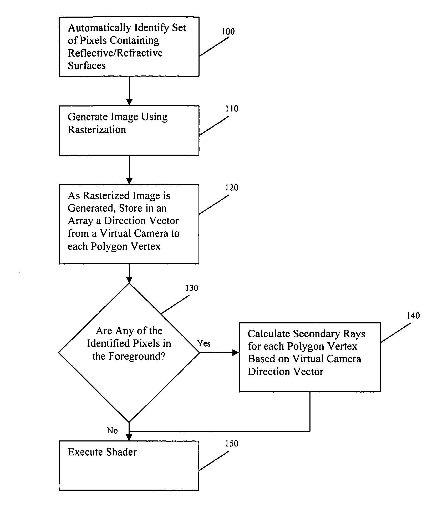
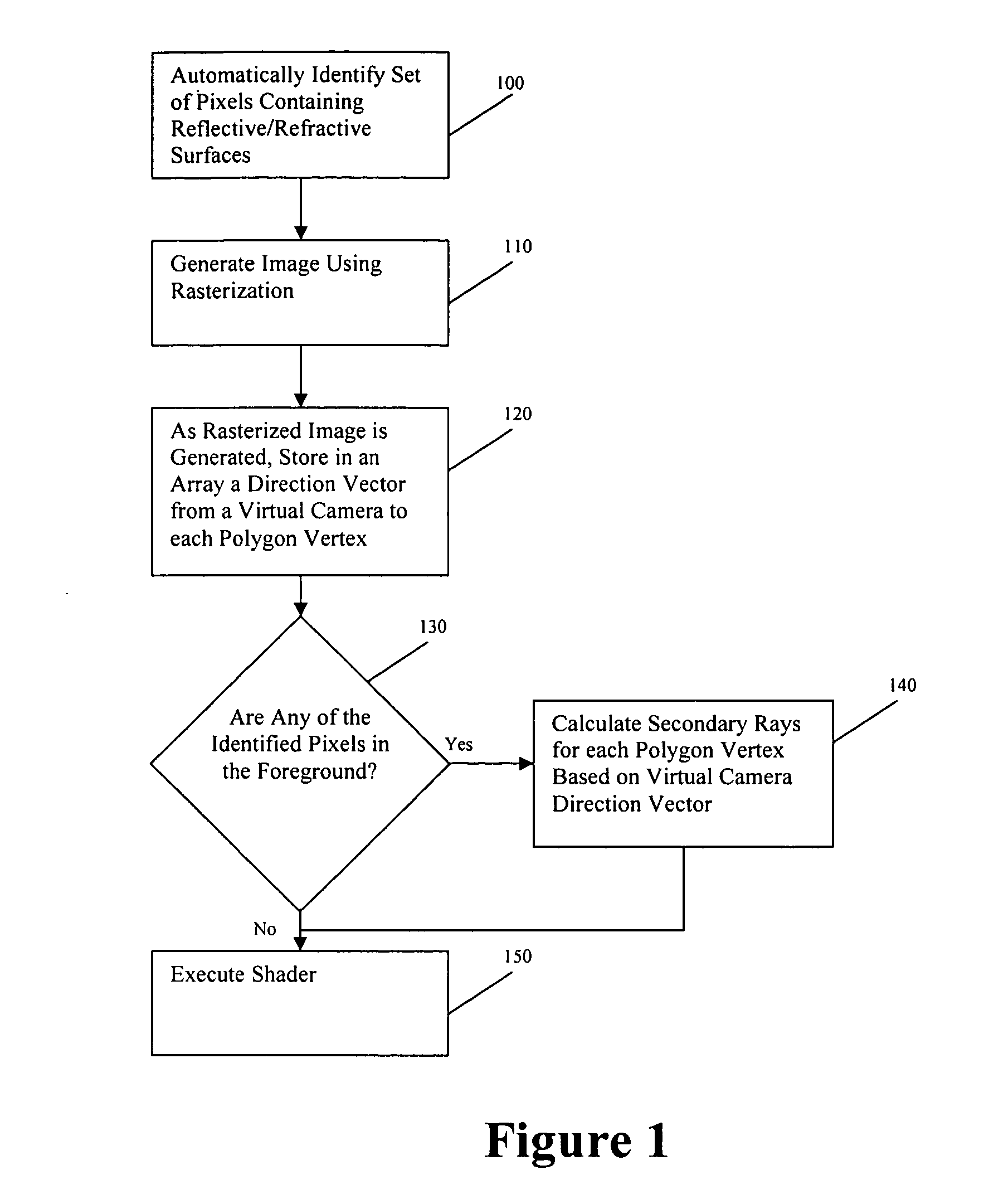
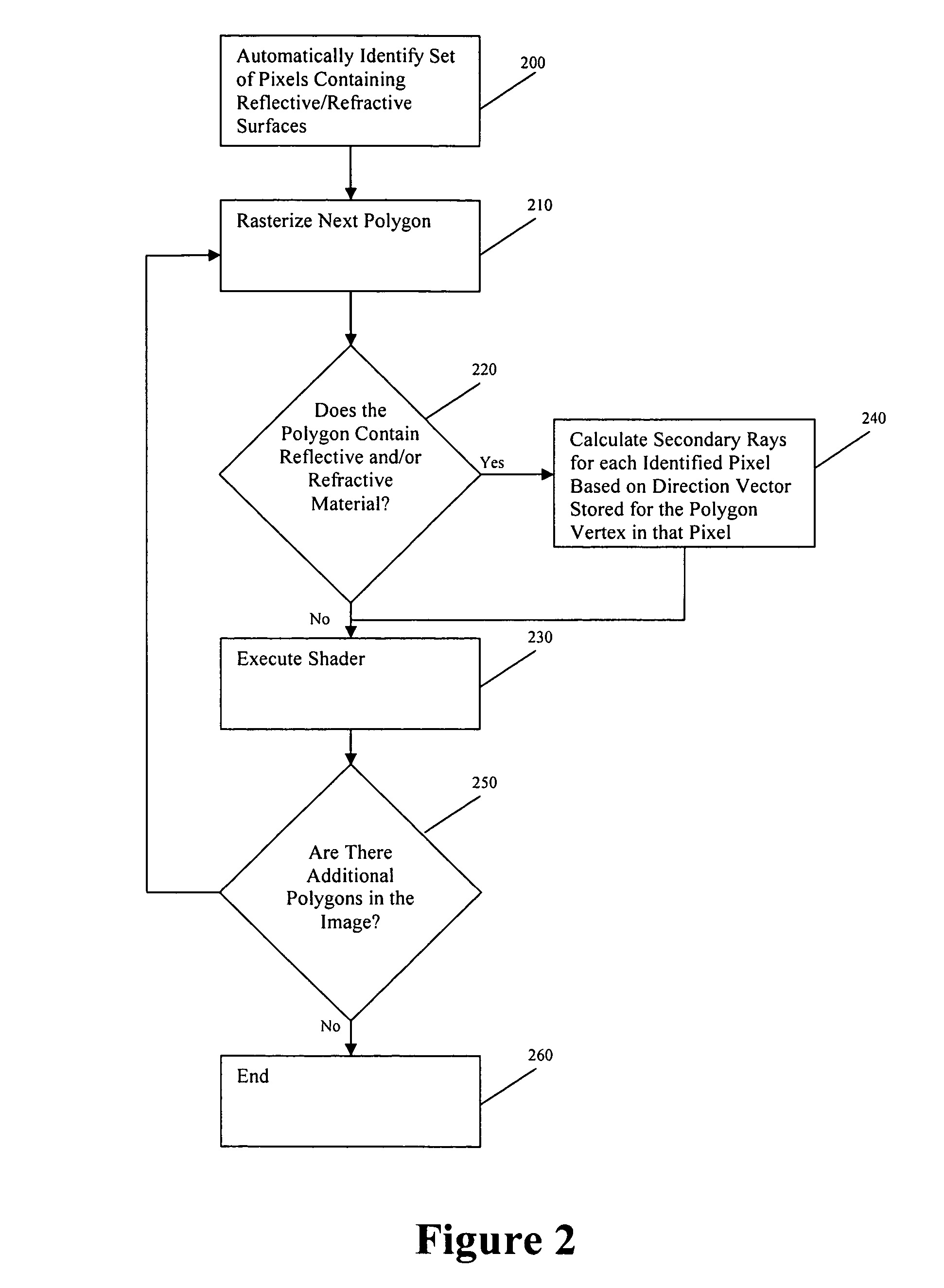
[0030] As described above, if only planar surfaces are to be considered, all rays (primary as well as secondary) can be seen as originating from one point, that of the virtual camera. Such an image could easily be generated using rasterization. However, if reflections, refractions, or other such optical distortions exist in the scene, such as, without limitation, those naturally occurring on curved surfaces such as vehicle windshields, all secondary rays originate from different points and it is therefore necessary to handle these rays separately using ray tracing.

[0031] In one embodiment, only selected surfaces where ray tracing effects (e.g. reflections or refraction) are apparent are rendered using ray tracing, with other parts of the image rendered using rasterization. More specifically, only secondary rays (those ref...


PUM


Abstract

A method of generating a computer image wherein secondary raytrace vectors are calculated for the image after the image is rendered using rasterization. The secondary raytrace vectors are based on virtual camera angles that are stored during the rasterization process. The raytrace vectors can be calculated using the same processor as the rasterization, thereby providing greater consistency in the image. A metaprogrammed shader can also be applied to the generated image, wherein the shader uses the same processor as the raytrace and rasterization steps. The metaprogrammed shader allows the shader algorithm to be segmented for streamlined processing by the processor.

Description

FIELD OF THE INVENTION [0001] The present invention relates to the field of computer-generated visualizations, and more specifically provides a method for efficiently rendering consistently shaded visualizations. BACKGROUND OF THE INVENTION [0002] Most computer graphics today use rasterization or raytracing to generate images. Rasterization and raytracing are two fundamentally different graphics techniques. In rasterization, all the modelling primitives used to describe the scene are projected towards the display, and the pixels covered by each primitive are determined. A per-pixel depth test is then applied to determine which primitive is visible in each pixel. This process is described in more detail by Tomas Akenine-Möller and Eric Haines, Real-Time Rendering, (2nd Ed., 2002). The second, raytracing, works backwards from the display. In raytracing, the modeling primitive that is visible in each pixel is determined by shooting rays into the scene. This process is described in more...

Claims


Application Information

Patent Timeline
Patent Type & Authority Applications(United States)
IPC IPC(8): G06T15/40
CPCG06T15/06G06T15/80G06T15/50G06T15/40
Inventor HEMPEL, SHAWNMCCOOL, MICHAEL
Owner DASSAULT SYST 3DEXCITE
Why Eureka
Try Eureka