Waterproof connector for flat cable

a flat cable, waterproof technology, applied in the direction of coupling device connection, contact member penetrating/cutting insulation/cable strand, securing/insulating coupling contact member, etc., can solve the problem of low productivity, electrical connection of the connecting portion can be disrupted, and the strength of the constricted portion of the mold can be lowered. problem, to achieve the effect of excellent waterproof condition and excellent reliability of electrical connection

Inactive Publication Date: 2007-02-15
YAZAKI CORP
View PDF3 Cites 23 Cited by
  • Summary
  • Abstract
  • Description
  • Claims
  • Application Information

AI Technical Summary

Benefits of technology

[0015] The present invention is made in view of the above-mentioned circumstances of the prior art. Thus, it is an object of the invention to provide a waterproof connector for a flat cable which not only can provide excellent reliability of the electrical connection between the flat cable and a terminal but also can provide an excellent waterproof condition between them.

Problems solved by technology

Normally, the male terminal 2a is secured within the male connector housing 5 and, therefore, the displacement of the flat cable 1a applies a load to the connecting portion between the flat cable la and male terminal, which can raise a fear that the electrical connection of the connecting portion can be disrupted.
However, the productivity thereof is not high.
And, when the two lips are formed so as to be closely contacted with the outer peripheral surface of a flat cable having a small thickness, there is a fear that the strength of the constricted portion of the mold can be lowered.
And, there is a feat that the lowered strength of the mold pieces constituting the mold can lower the productivity of the seal members and thus can lower the productivity of the connector.

Method used


Image

  • Waterproof connector for flat cable
  • Waterproof connector for flat cable
  • Waterproof connector for flat cable

Examples


first embodiment

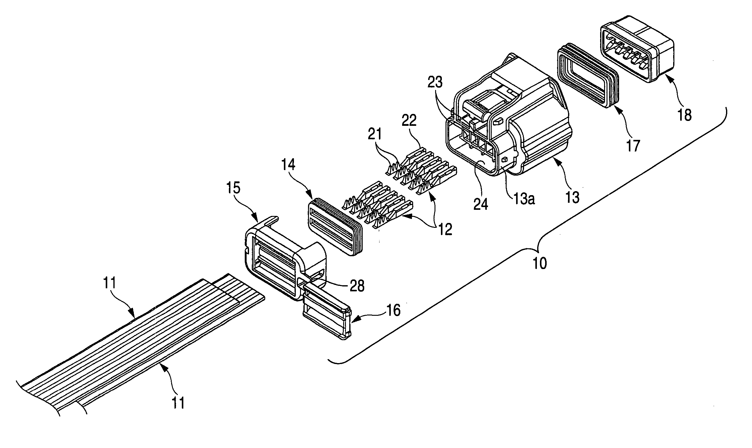
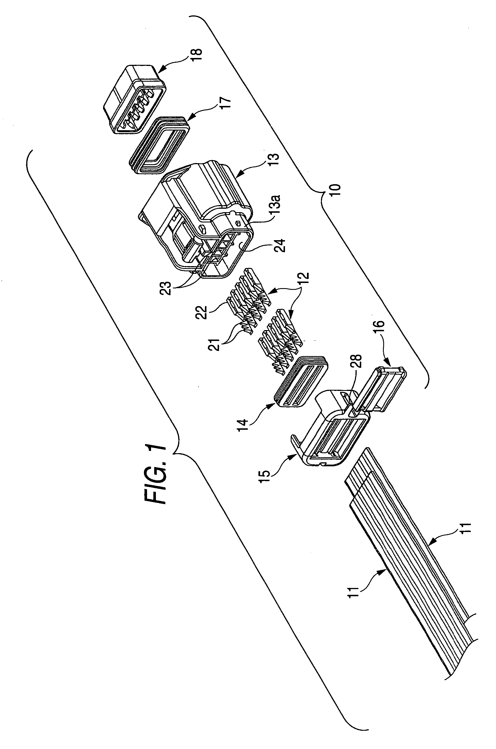
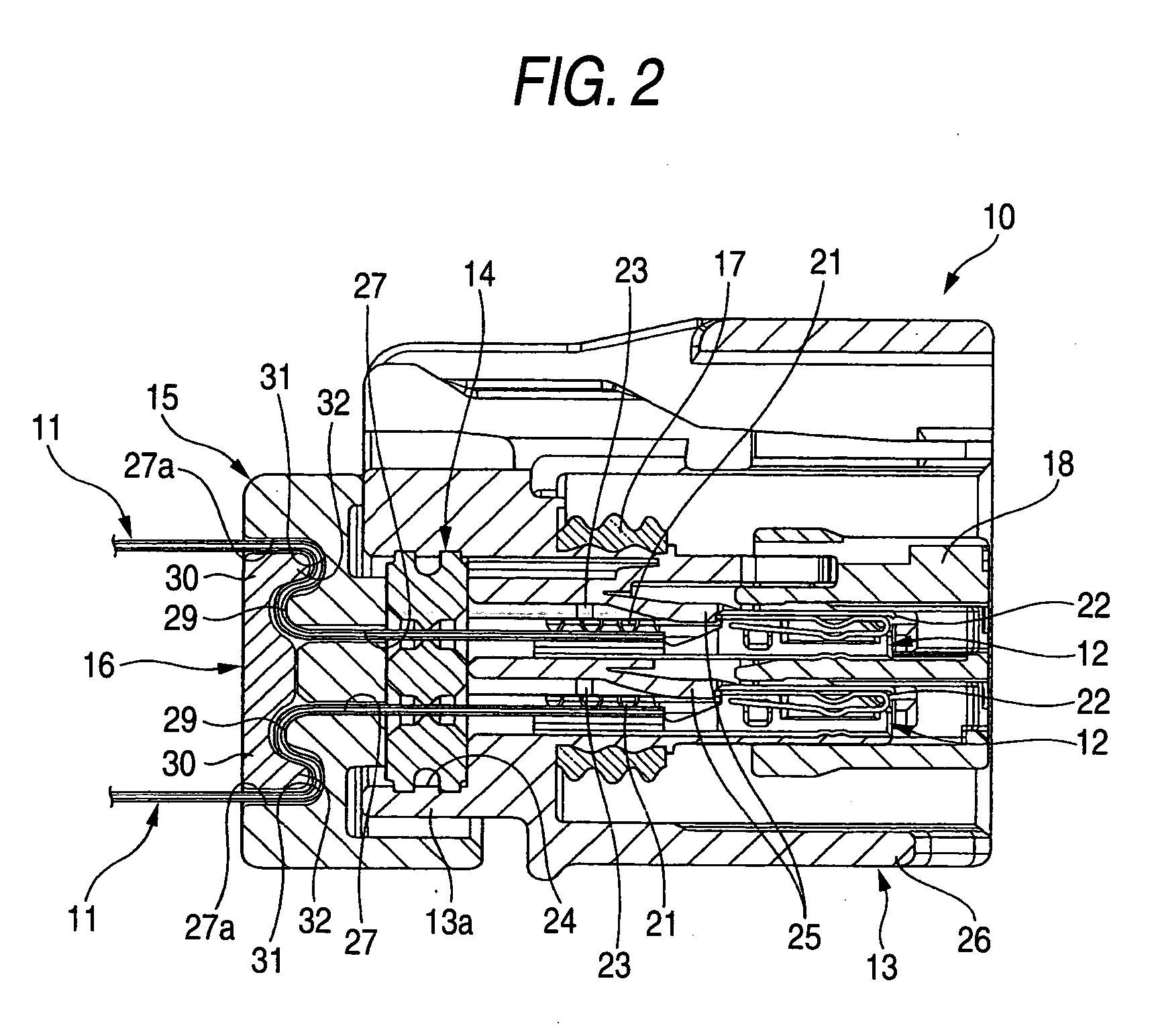
[0053] As shown in FIGS. 1 and 2, a waterproof connector for a flat cable (which is hereinafter referred to as a connector simply) 10 is mounted on the terminal portions of two FFCs 11 disposed parallel to each other while they are spaced apart from each other in the thickness direction thereof. The connector 10 includes two or more terminals 12 to be connected to the terminal portions of the FFCs 11, a connector housing 13 for storing the two or more terminals 12 therein, a seal member 14 for providing a waterproof condition between the FFCs 11 and connector housing 13, a rear cover 15 to be mounted on to the connector housing 13, and a fixing plate 16 to be mounted onto the rear cover 15.

[0054] To produce the FFC 11, for example, two or more long conductors made of rolled copper foil may be held parallel by and between base films at given intervals and may be then unified together. To the terminal portion of the FFC11, there are connected the two or more terminals 12 which are to...

second embodiment

[0068] Next, description will be given below of a waterproof connector (which is hereinafter referred to as a connector simply) for a flat cable according to a second embodiment of the invention with reference to FIGS. 3 and 4. By the way, a connector according to the second embodiment is different from the above-mentioned connector 10 according to the first embodiment only in a rear cover and a fixing plate, but the other remaining components thereof are the same and thus the description thereof is omitted here.

[0069] As shown in FIGS. 3 and 4, a rear cover 35 according to the present embodiment includes two insertion holes 47 which are arranged in two stages and are formed to have a section shape slightly larger than the section shape of the FFC 11. The rear cover 35, while inserting two FFCs 11 extended from the guide holes 24 of the connector housing 13 into these insertion holes 47 respectively, is mounted onto the base end portion of the connector housing 13 so as to cover th...

third embodiment

[0074] Next, description will be given below of a waterproof connector (which is hereinafter referred to as a connector simply) for a flat cable according to a third embodiment of the invention with reference to FIGS. 5 and 6. By the way, a connector according to the second embodiment is different from the above-mentioned connector 10 according to the first embodiment only in a rear cover and a fixing plate, but the other remaining components thereof are the same and thus the description thereof is omitted here.

[0075] As shown in FIGS. 5 and 6, a rear cover 65 according to the present embodiment includes two insertion holes 77 which are arranged in two stages and are formed to have a section shape slightly larger than the section shape of the FFC 11. The rear cover 65, while inserting two FFCs 11 extended from the guide holes 24 of the connector housing 13 into these insertion holes 77 respectively, is mounted onto the base end portion of the connector housing 13 so as to cover the...


PUM


Abstract

A waterproof connector for a flat cable 10 includes a connecting housing 13 into which the terminal portions of two FFCs 11 can be guided through a guide hole 24 formed in the base end portion thereof and also which can store therein two or more terminals 12 connected to the terminal portions of the FFCs 11, a seal member 14 interposed between the FFCs 11 and the peripheral wall of the connector housing 13 for defining the guide hole 24, a rear cover 15 not only including two insertion holes 27 into which the FFCs 11 extended from the guide hole 24 of the connector housing 13 can be inserted but also mountable onto the base end portion of the connector housing 13 while inserting the FFCs 11 into the insertion holes 27, and a fixing plate 16 to be mounted onto the rear cover 15 in such a manner that the FFCs 11 inserted into the insertion holes of the rear cover 15 are held by and between the rear cover 15 and the fixing plate 16.

Description

BACKGROUND OF THE I INVENTION [0001] 1. Field of the Invention [0002] The present invention relates to a waterproof connector for a flat cable which can be mounted on the terminal portion of a flexible flat cable such as an FFC (Flexible Flat Cable) and a ribbon line. [0003] 2. Description of the Related Art [0004] As an example of a conventional waterproof connector for a flat cable, there is known a connector shown in FIG. 7 (see Japanese Patent Publication Hei 6-5327, for example). [0005] In FIG. 7, there are shown a male side connector and a female side connector of a waterproof connector for a flat cable. The terminal portion of a flat cable la with a male terminal 2a connected thereto and the terminal portion of a flat cable 1b with a female terminal 2b connected thereto are respectively stored within a male connector housing 5 and a female connector housing 6. [0006] On the flat cables 1a, 1b, there are provided resin formed portions 3a, 3b which are respectively formed by bu...

Claims


Application Information

Patent Timeline
Patent Type & Authority Applications(United States)
IPC IPC(8): H01R11/20
CPCH01R13/5205H01R12/778
Inventor IWAHORI, YOSHIHIRO
Owner YAZAKI CORP
Why Eureka
Try Eureka