Method and apparatus for displaying a color flow image in an ultrasound diagnostic system

a color flow image and ultrasound diagnostic technology, applied in the field of ultrasonic diagnostic systems, can solve the problems that the person unskilled in the conventional diagnostic system cannot accurately analyze the 2-dimensional color doppler image, and the conventional ultrasound diagnostic system cannot provide accurate information of blood flow, so as to achieve accurate display of target blood flow

Active Publication Date: 2007-02-15
MEDISON CO LTD
View PDF4 Cites 11 Cited by
  • Summary
  • Abstract
  • Description
  • Claims
  • Application Information

AI Technical Summary

Benefits of technology

[0006] The present invention provides an apparatus and a method for performing a transparency treatment for blood flow images with predetermined transparency in the 3-dimensional color flow image to accurately display a target blood flow in an ultrasound diagnostic system.

Problems solved by technology

Since the conventional diagnostic system displays the color Doppler image, which indicates the velocities of the moving target object and the scatters, on a 2-dimensional level, there is a problem in that a person unskilled in the conventional diagnostic system cannot accurately analyze the 2-dimensional color Doppler image.
Therefore, there is a problem in that the conventional ultrasound diagnostic system cannot provide accurate information of the blood flows.

Method used


Image

  • Method and apparatus for displaying a color flow image in an ultrasound diagnostic system
  • Method and apparatus for displaying a color flow image in an ultrasound diagnostic system
  • Method and apparatus for displaying a color flow image in an ultrasound diagnostic system

Examples


Embodiment Construction

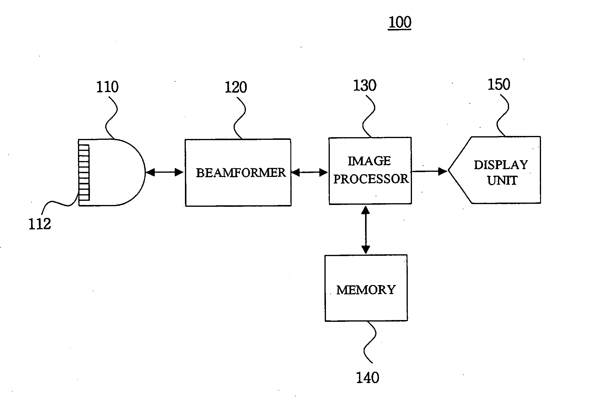
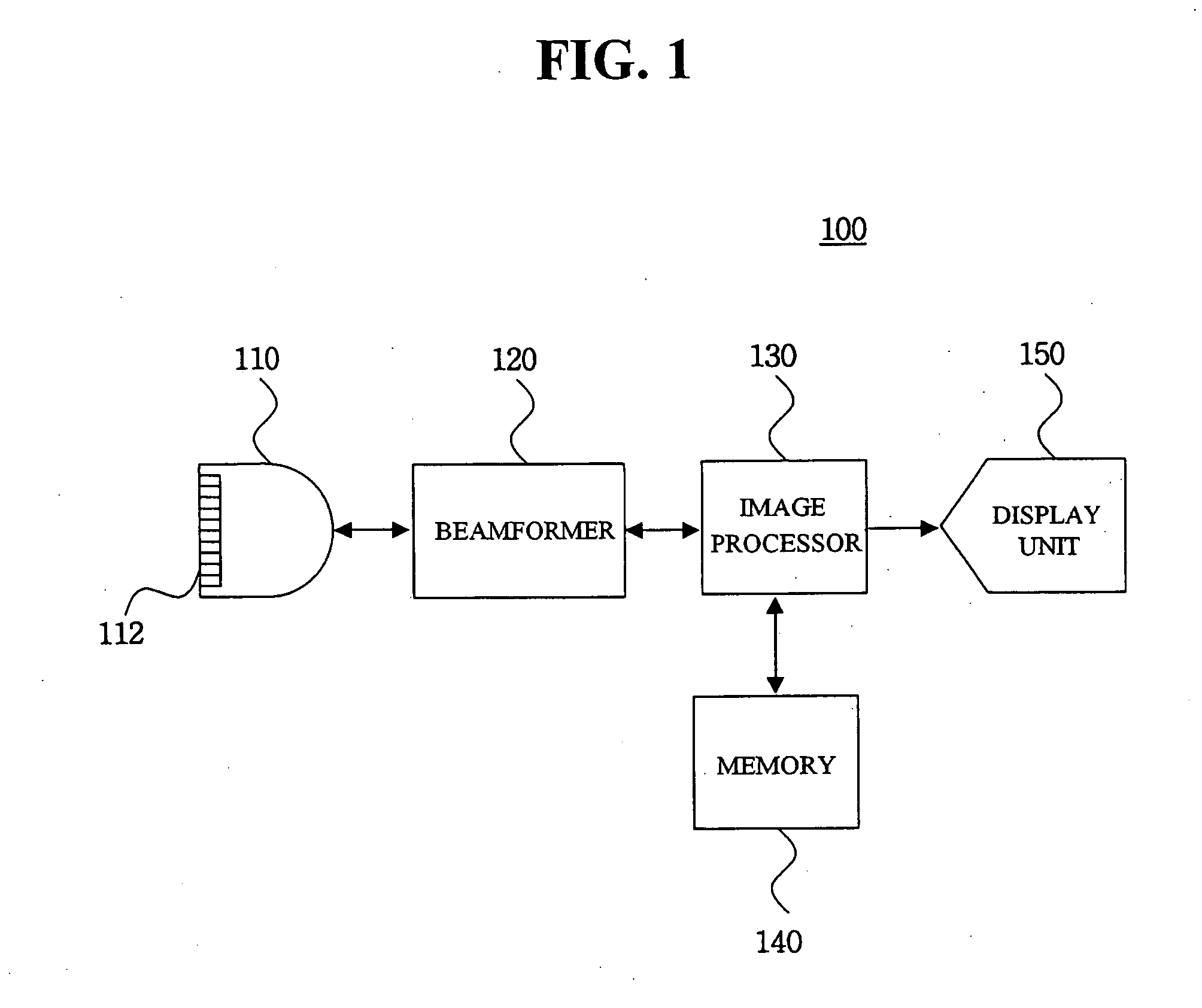
[0014]FIG. 1 is a block diagram showing an ultrasound diagnostic system 100, which is constructed in accordance with the preferred embodiment of the present invention. As shown in FIG. 1, the ultrasound diagnostic system 100 includes a probe 110, a beam former 120, an image processor 130, a memory 140 and a display unit 150.

[0015] The probe 110 includes a 1-dimensional or 2-dimensional array transducer 112. The transmit signals, which are appropriately delayed to form a focused ultrasound beam in the beam former 120, are transmitted to the array transducer112 and the focused ultrasound beam is transmitted along a scan line of a target object (not shown). The probe 110 receives ultrasound echo signals reflected from the target object and converts the ultrasound echo signals into electric signals (hereinafter referred to as reception signals). The reception signals are transmitted into the beam former 120.

[0016] The beam former 120 controls the delay of transmit signals to be transm...


PUM


Abstract

The present invention relates to a method and an ultrasound diagnostic system for displaying a 3-dimensional color flow image performing a transparency treatment for a predetermined region. The method of displaying a color flow image, comprises: a) forming a plurality of 2-dimensional color flow images based on ultrasound echo signals; b) sequentially superposing the plurality of 2-dimensional color flow images to form a 3-dimensional color flow image including a plurality of image regions; c) receiving selection information for selecting a desirable image region from the 3-dimensional color flow image; and d) performing a transparency treatment upon the selected region in the 3-dimensional color flow to have a predetermined transparency.

Description

FIELD OF THE INVENTION [0001] The present invention generally relates to ultrasound diagnostic systems, and more particularly to an apparatus and method for displaying a color flow image in an ultrasound diagnostic system. BACKGROUND OF THE INVENTION [0002] Generally, an ultrasound diagnostic system projects ultrasound signals from a surface of a target object toward a desired part within the target object. This is to obtain an ultrasound image of a soft tissue or blood flow by non-invasive means through using information of ultrasound echo signals from the target object. Compared to other medical imaging systems (e.g., X-ray diagnostic system, X-ray CT scanner, MRI and nuclear medicine diagnostic system), the ultrasound diagnostic system is advantageous since it is small in size and fairly inexpensive. Further, the ultrasound diagnostic system is capable of providing real-time display and is highly safe without any dangerous side effects such as exposure to X-rays, etc. Thus, it is...

Claims


Application Information

Patent Timeline
Patent Type & Authority Applications(United States)
IPC IPC(8): A61B8/00
CPCA61B8/06A61B8/483G06T15/503G06T2219/2012G06T2210/24G06T2210/62G06T19/20A61B8/00
Inventor HYUN, DONG GYU
Owner MEDISON CO LTD
Why Eureka
Try Eureka