Method and control plane for provisioning connections in a multi-layer transport network

a multi-layer transport network and control plane technology, applied in the field of telecoms, can solve the problems of complex recovery scenarios, communication overhead, and the work of the gmpls routing mechanism, and achieve the effect of simply changing the cost structur

Inactive Publication Date: 2007-02-15
RPX CORP
View PDF5 Cites 6 Cited by
  • Summary
  • Abstract
  • Description
  • Claims
  • Application Information

AI Technical Summary

Benefits of technology

[0011] The invention allows to use available bandwidth in a very efficient way shared by different service layers. Moreover, thanks to the new routing mechanism, the available bandwidth ...

Problems solved by technology

However, GMPLS routing mechanisms work only on a single network layer.
This creates communication overhead and leads to complex recovery scenarios.
However, since in this solution server layer conne...

Method used


Image

  • Method and control plane for provisioning connections in a multi-layer transport network
  • Method and control plane for provisioning connections in a multi-layer transport network
  • Method and control plane for provisioning connections in a multi-layer transport network

Examples


first embodiment

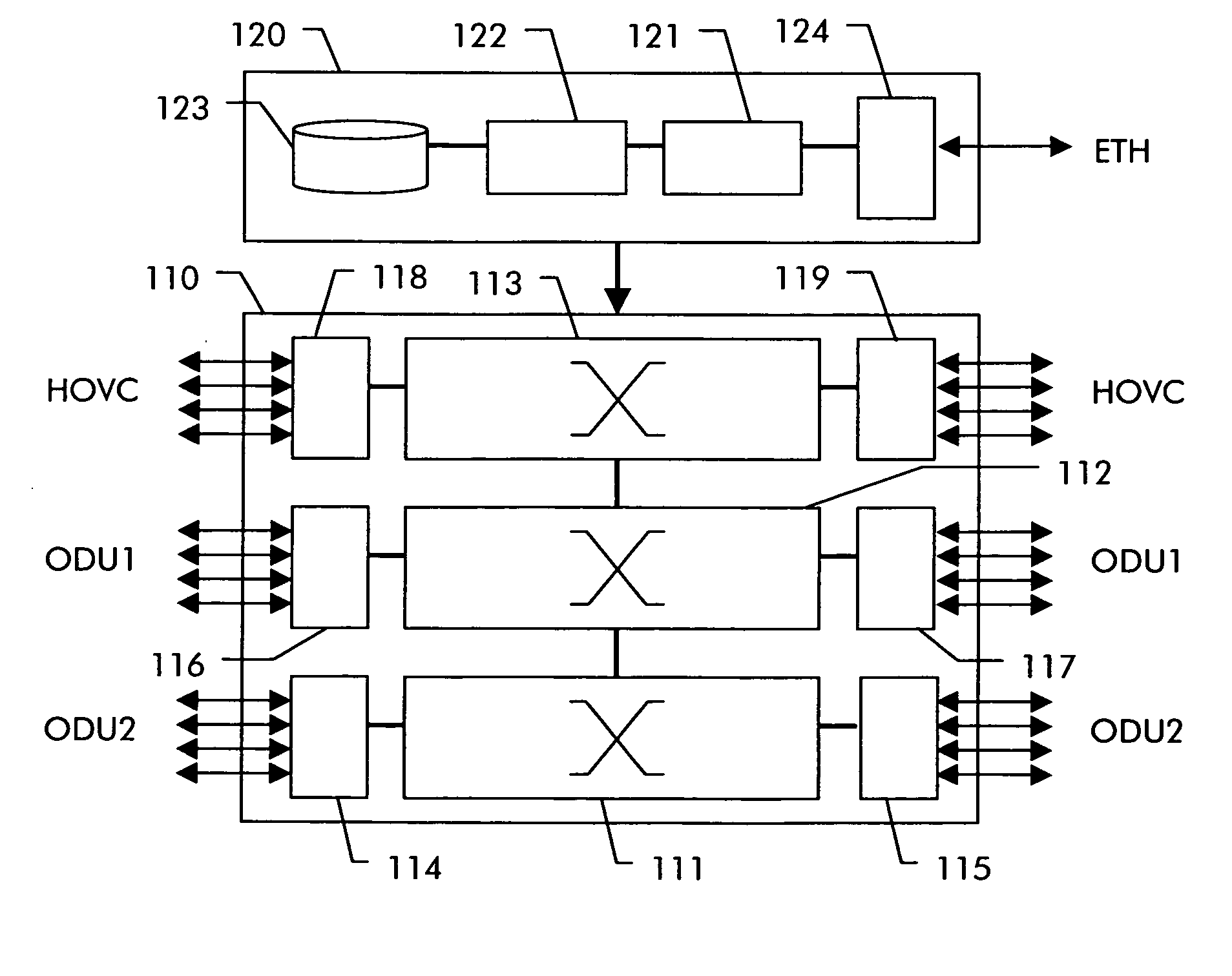
[0036] In the first embodiment, switching within the network is performed on client layer level, i.e., HOVC is switched on HOVC level at each hop between source and destination, ODU1 on ODU1 level and so on. As a general rule, if no server layer resources to the next hop are already provisioned, the smallest server level container will be used. This rule serves to avoid a need to negotiate the type of a server layer connection to be created. It should be clear, however, that any other predefined rule can be used instead or the server layer connection type can be negotiated.

[0037] According to the invention, routing is performed on cost per link basis but it is taken into account that also higher layer capacity is available for lower layer connections. In other words, the algorithm pretends that server layer connections were available even if not yet existing. Routing information is based on available capacity per layer. As long as only links are selected for a path, where server lay...

second embodiment

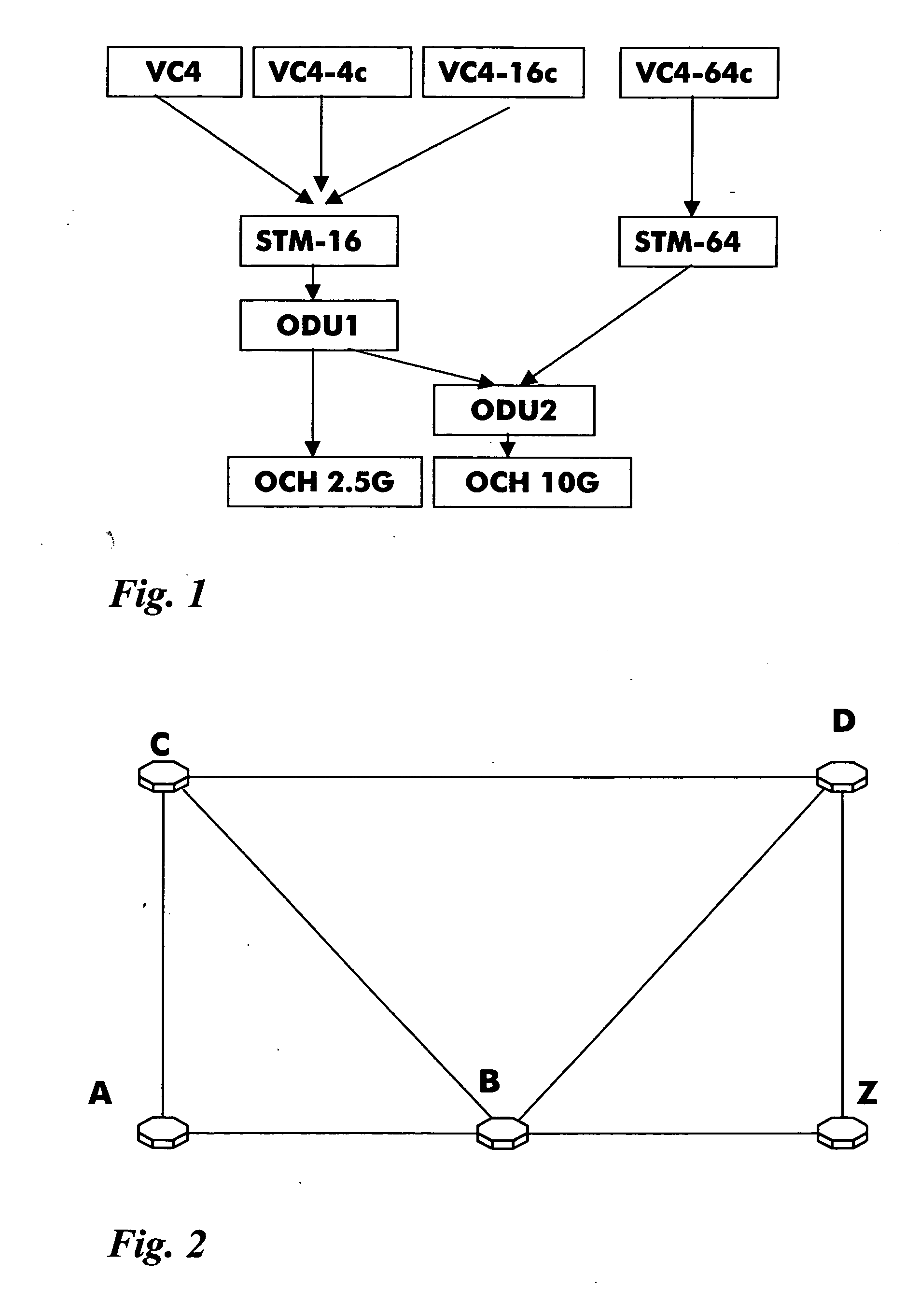
[0049] Further aspects of are now explained in a second embodiment, which uses the same network topology shown in FIG. 2.

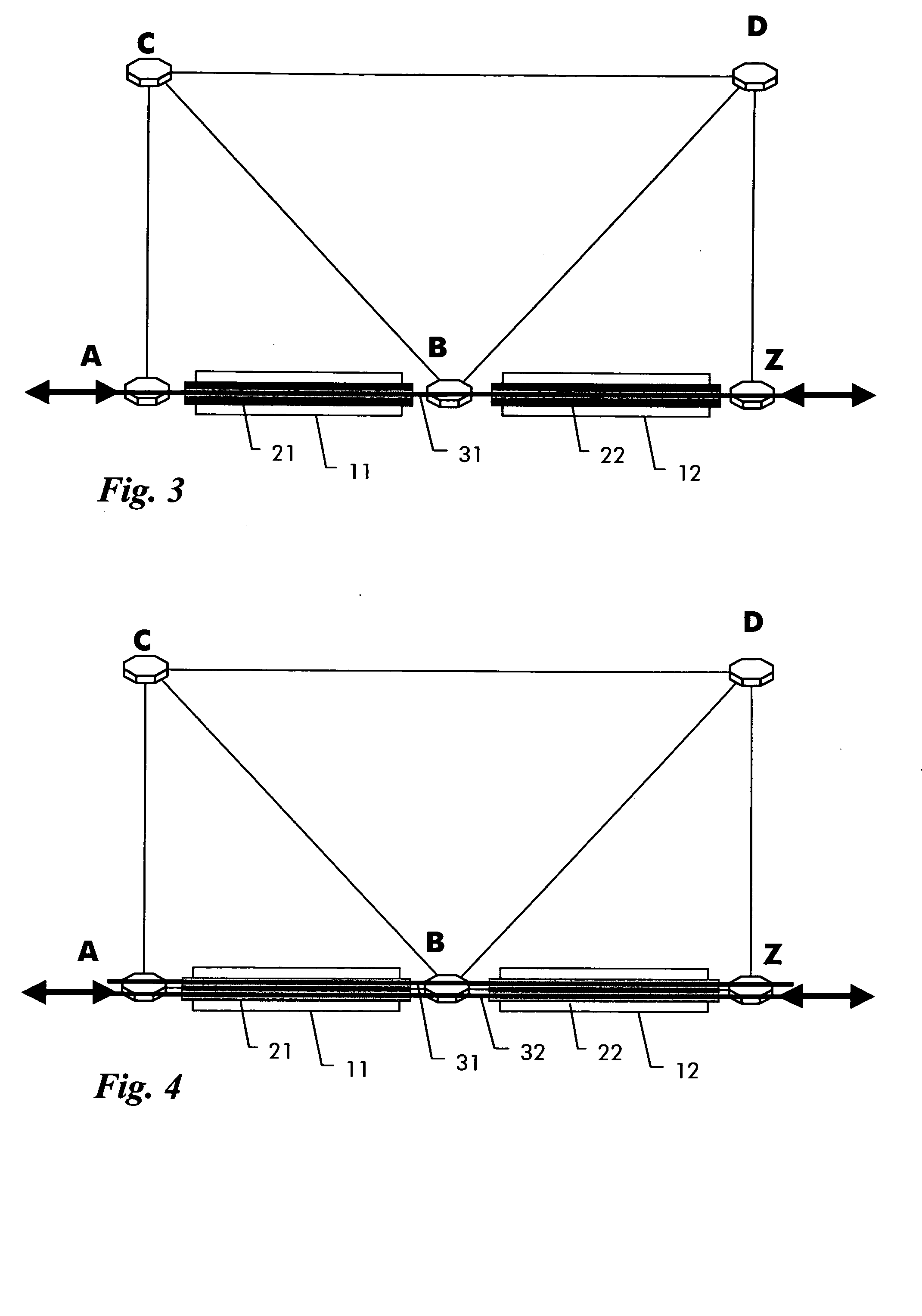
[0050] The limitation of the first embodiment is that automatically created connections do not trigger multi-hop server trails but only single hop server trails. It is generally more efficient if multi-hop server trails, which we call forwarding adjacencies (FAs), are generated, but the policy to create them can become more complex. A simplified policy will be proposed below based on the expectation that an operator provisioned multi-hop forwarding adjacency is optimal.

[0051] A general rule of this improvement is that, if between a source and destination node A-Z a direct forwarding adjacency exists but which has no idle capacity, an additional server trail is created along the same links. Along these links the same cost metrics apply as described for the first embodiment. If the new server trail, however, cannot use the same route, different policies can be appl...


PUM


Abstract

In a multi-layer transport network, a method and related control plane allow automatic provisioning of a client layer connection (31, 32, 33, 24, 34, 35) over at least one server layer connection (11, 12, 13, 21, 22, 23, 14, 15, 16, 25, 26) by selecting a path through the transport network taking into account free resources of existing server layer connections (14, 15, 16, 25) and additionally taking into account free resources in the transport network, where no server layer connections exist so far. The selection is based on a cost calculation which takes into account a cost value per link and further takes into account an additional cost value for links on which no available server layer connection exist so far. Eventually, the path having the lowest overall cost is selected. Server layer connections (11, 12, 13, 21, 22, 23, 26) on links along said selected path where no server layer connection with free resources exists so far are then established and used to set up the requested client layer (31, 32, 33, 24, 34, 35) connection.

Description

[0001] The invention is based on a priority application EP 05291730.9 which is hereby incorporated by reference. FIELD OF THE INVENTION [0002] The present invention relates to the field of telecommunications and more particularly to a method and related control plane for automatically provisioning connections in a multi-layer transport network. BACKGROUND OF THE INVENTION [0003] Transport networks are for example networks based on SDH (Synchronous Digital Hierarchy) as defined in ITU-T G.707 12 / 2003 or OTH (Optical Transport Hierarchy) as defined in ITU-T G.709 03 / 2003. These ITU-T recommendations are both incorporated by reference herein. Such transport networks have a multi-layer multiplex hierarchy where higher layer transport signals serve for the transport of either tributary signals or lower layer transport signals, which can then transport tributary signals at a lower rate. A higher layer is thus referred to as a server layer and a lower layer as a client layer. [0004] For ex...

Claims


Application Information

Patent Timeline
IPC IPC(8): G06F15/173
CPCH04L45/12
Inventor GRAMMEL, GERT
Owner RPX CORP
Why Eureka
Try Eureka