Machine for printing on hollow bodies

Inactive Publication Date: 2007-02-22
HINTERKOPF
View PDF4 Cites 13 Cited by
  • Summary
  • Abstract
  • Description
  • Claims
  • Application Information

AI Technical Summary

Problems solved by technology

Since for this switching of position a certain minimum time is necessary, in many cases it will not be possible to avoid the rotary screen coming into

Method used


Image

  • Machine for printing on hollow bodies
  • Machine for printing on hollow bodies
  • Machine for printing on hollow bodies

Examples


working embodiment

. WORKING EMBODIMENT OF THE INVENTION

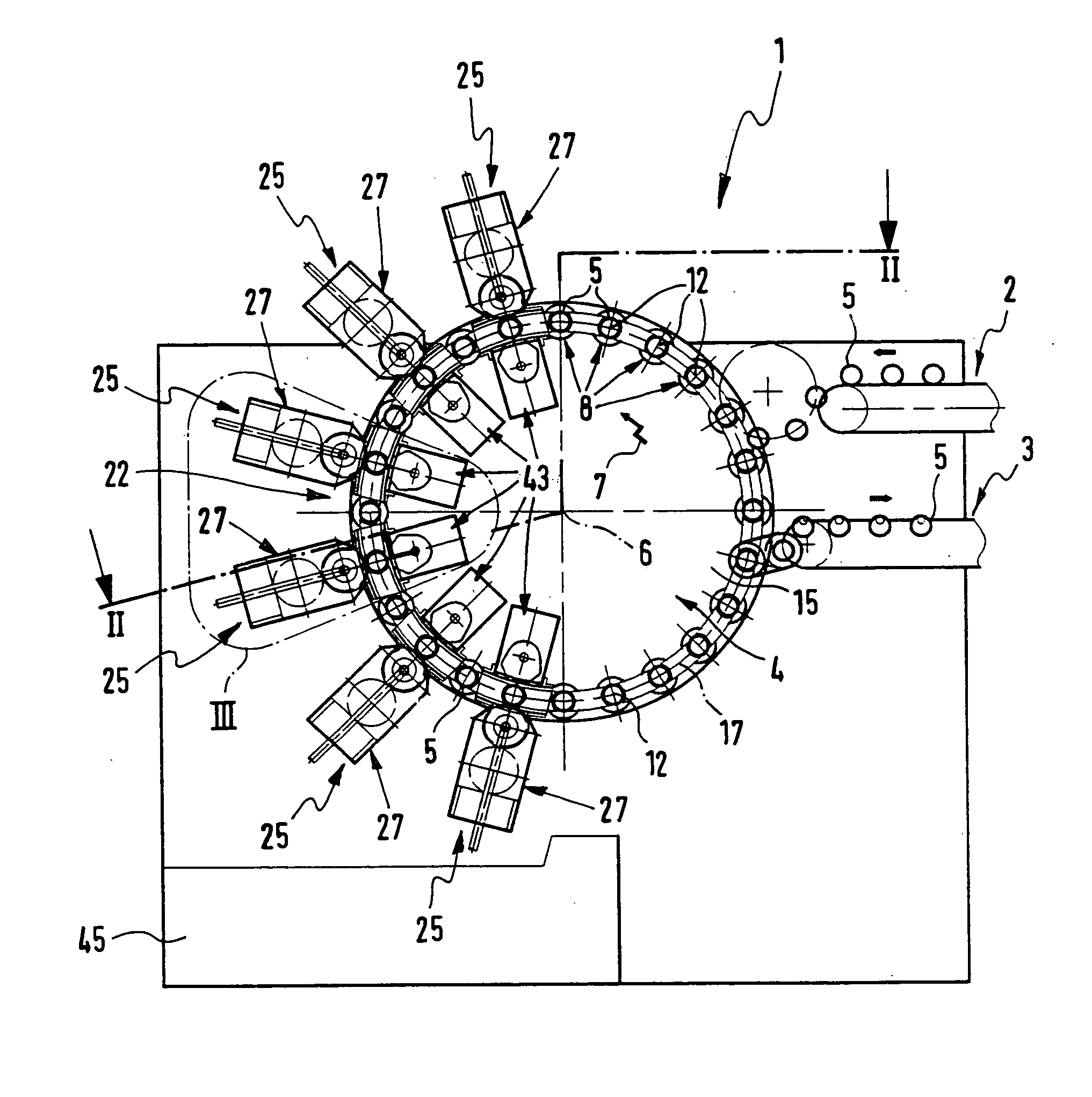
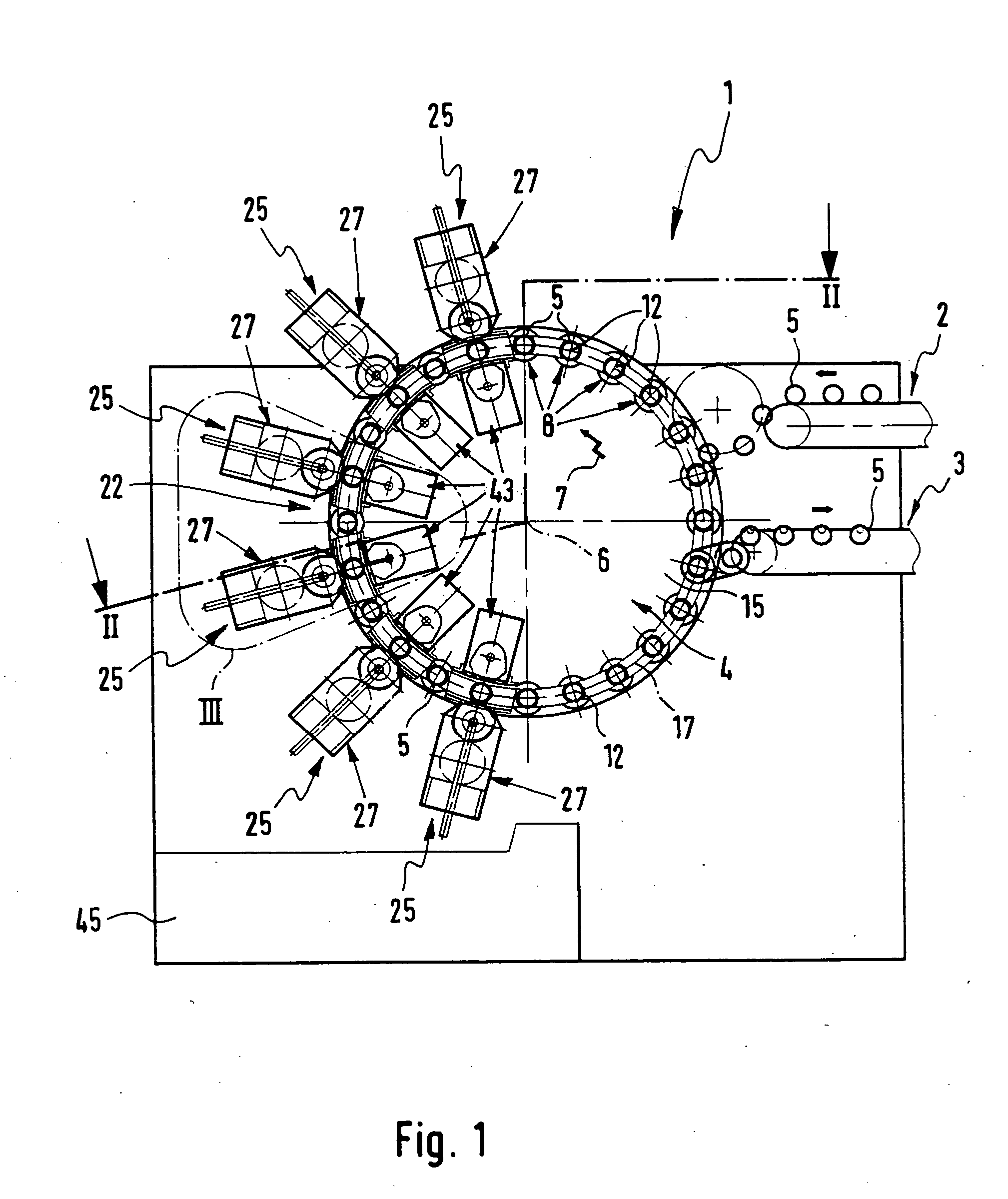
[0027] The printing machine generally referenced 1 as a whole comprises inter alia a supply conveying means 2 and a removal conveying means 3, which are respectively associated with the peripheral portion of a receiving spindle 4 able to be caused to rotate in steps by a drive, which is not illustrated in detail. By means of the supply conveying means 2 hollow bodies 5 to be printed can be supplied. Using the removal conveying means 3 already printed hollow bodies 5 may be taken over by the spindle plate 4 and cleared from the system.

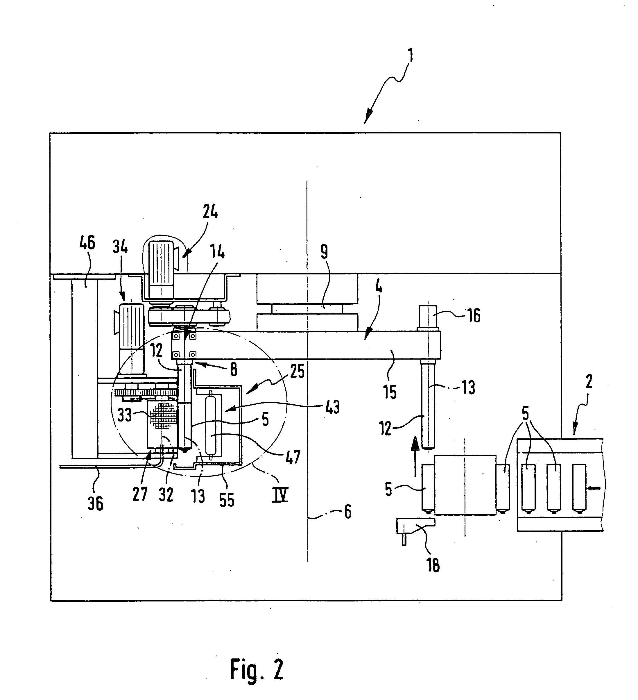
[0028] As regards details the spindle plate 4 may be driven in steps as a rotary movement about the axis of rotation 6 with a direction of rotation 7 indicated by the jagged arrow 7. The axis 6 of rotation is horizontal in direction. The spindle plate 4 is mounted for rotation about a hub 9 on the machine frame 45.

[0029] The spindle plate 4 is provided with a plurality of spindle units 8 following each other in the...


PUM


Abstract

A machine for printing on hollow bodies such as sleeves, collapsible tubes, cans or the like, comprises receiving spindles having a horizontal axis of rotation on which receiving spindles are arranged which precede along a spindle track curve during stepped rotational movement of the spindle plate. Along this spindle track curve a plurality of combined printing and drying stations are distributed, which each possess a rotary screen printing mechanism for printing on hollow bodies mounted on the receiving spindles and a radiation dryer for drying ink applied to the hollow bodies. Within the printing and drying stations the rotary screen printing mechanism and the radiation dryer are respectively opposite one another, the latter being so designed that same may simultaneously act on the receiving spindle located at the time in the associated printing and drying station.

Description

BACKGROUND OF THE INVENTION [0001] The invention relates to a machine for printing on hollow bodies such as sleeves, collapsible tubes, cans or the like, comprising: [0002] a spindle plate able to be rotated in steps and having a horizontal axis of rotation, which spindle plate bears spindle units following each other with a clearance in succession in the direction of rotation, such spindles respectively possessing a receiving spindle aligned parallel to the axis of rotation, and able to mount the respective hollow body to be printed and which during rotation of the spindle plate describe a spindle track curve, [0003] a plurality of printing stations distributed along the spindle track curve, which respectively possess a rotary screen printing mechanism having a tubular rotary screen aligned in parallelism to the receiving spindles, such rotary screen being adapted to make rolling engagement with the outer periphery of the hollow body positioned at the time in the respective printin...

Claims


Application Information

Patent Timeline
IPC IPC(8): B41F17/00
CPCB41F15/12B41F15/0872
Inventor AICHELE, HELMUTFRANK, MARTIN
Owner HINTERKOPF
Why Eureka
Try Eureka