Compact membrane unit and methods

a membrane unit and compact technology, applied in membrane technology, membranes, reverse osmosis, etc., can solve the problems of limited functional requirements for the placement of feed lines, residue lines, permeate lines with respect to each of the tubes or housings, and achieve the effect of low friction

Inactive Publication Date: 2007-02-22
ASHFORD EDMUNDO R
View PDF59 Cites 55 Cited by
  • Summary
  • Abstract
  • Description
  • Claims
  • Application Information

AI Technical Summary

Benefits of technology

[0024] In yet another embodiment, the membrane unit tubular walls may further comprise an internal low friction coating for sealing engagement with respective of the plurality membrane cartridges that permits relatively low friction axial movement of the membrane cartridges along the tubular walls.

Problems solved by technology

The possible placement of the feed line, residue line, and permeate lines with respect to each of the tubes or housings is limited by functional requirements.

Method used


Image

  • Compact membrane unit and methods
  • Compact membrane unit and methods
  • Compact membrane unit and methods

Examples


Embodiment Construction

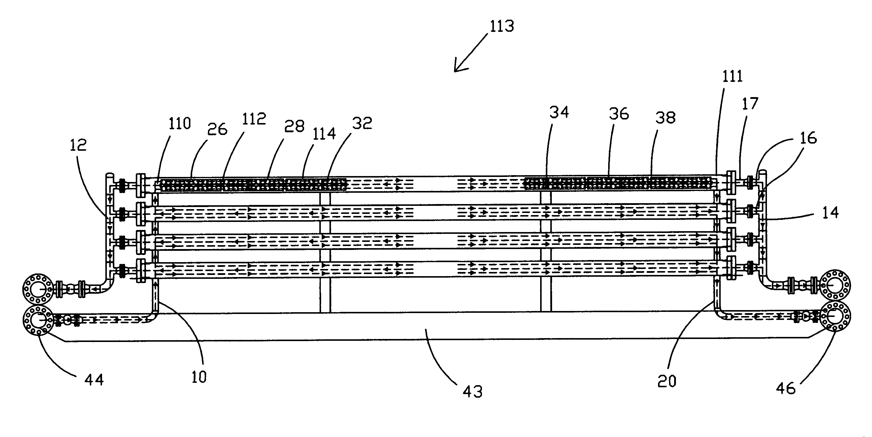
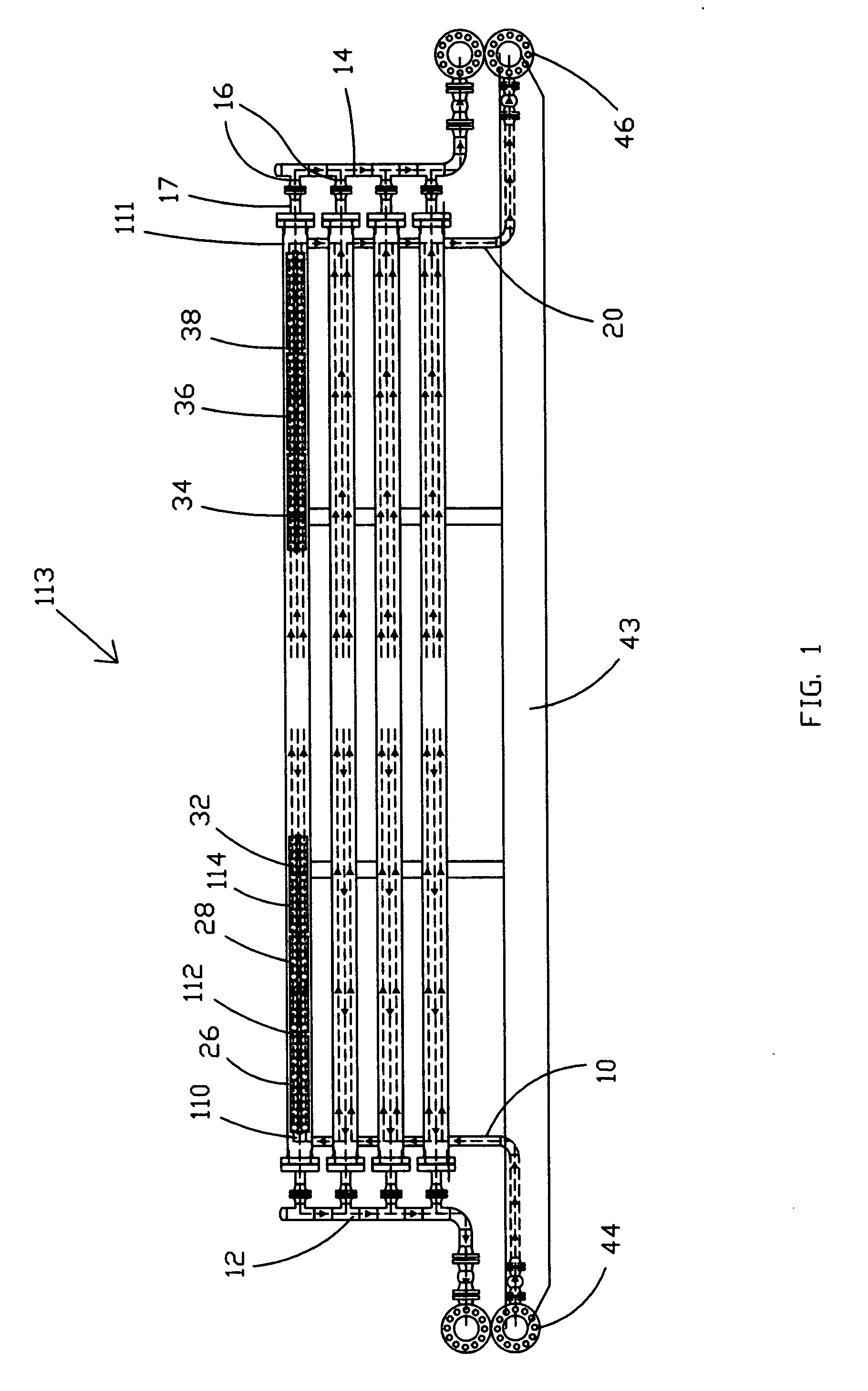
[0037] The present invention involves use of membrane units such as membrane unit 113 shown in FIG. 1. Prior art membrane units utilize headers for the feed line, residue line, and the permeate line. For instance, a typical prior art permeate header may be of the type of header as permeate header 12 shown in FIG. 1. However, in one embodiment of the present invention, the feed header and reside header are constructed in a considerably less expensive and less bulky manner. Thus, in one embodiment of the present invention, what may be referred to as a pseudo-header is provided. The use of feed pseudo-header 10 and residue pseudo-header 20, which in this example also incorporates buried portions 44 and 46 as discussed hereinafter, provides the benefits of a standard header as commonly used in the art, but at costs that are significantly reduced. At the same time, the pseudo-header results in a decrease in the size / weight of the membrane unit.

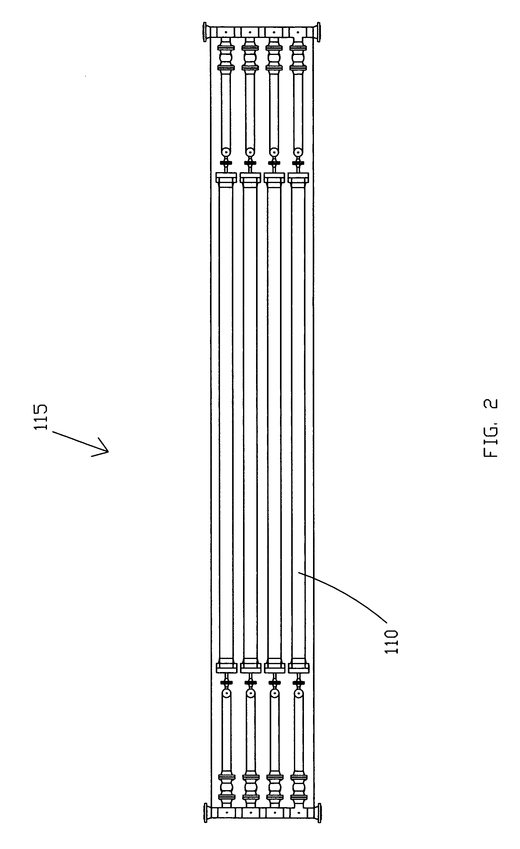
[0038] The multiple membrane housing arrays...


PUM


Abstract

Modular or cartridge-type membrane units utilize hollow, cylindrical tubular housings or receivers to house strings of removable membrane modules (elements) and normally comprise arrays of pipes that act as membrane module housings. A pseudo header for fluidly interconnecting the array of pipes reduces weight and cost. The pseudo header may comprise portions that are buried within skid components such as the toe bar. An internal low friction coating permits a larger number of membrane cartridges to be utilized in any cylindrical tubular membrane housing. A center feed pseudo header permits flow in two directions through the tubular membrane housing to double hydraulic capacity.

Description

[0001] This application claims priority from U.S. Provisional Patent Application No. 60 / 710,258, filed Aug. 22, 2005.BACKGROUND OF THE INVENTION [0002] 1. Field of the Invention [0003] The present invention relates generally to membrane treating systems and, more particularly, to systems and methods for maximizing treating capacity while reducing the physical dimensions of height, width, depth, and footprint, and / or overall weight of a membrane unit. [0004] 2. Description of the Background [0005] Membrane treating systems are often utilized in remote locations and locations where significant space and weight limitations apply. Membrane treating systems are often skid-mounted for easier transportation. Membrane units have a feed line of fluid (e.g. gas and / or liquid) to be treated, a residue line, and a permeate line. In natural gas membrane treating systems, typically the residue line is the treated gas output and the permeate line is the vented wastes, which may be flared. In vario...

Claims


Application Information

Patent Timeline
Patent Type & Authority Applications(United States)
IPC IPC(8): B01D61/00
CPCB01D61/00B01D61/02B01D61/14B01D2317/04B01D2313/06B01D2313/20B01D65/00
Inventor ASHFORD, EDMUNDO R.
Owner ASHFORD EDMUNDO R
Why Eureka
Try Eureka