Active cooling substrate support

Active Publication Date: 2007-02-22
APPLIED MATERIALS INC
View PDF65 Cites 67 Cited by
  • Summary
  • Abstract
  • Description
  • Claims
  • Application Information

AI Technical Summary

Benefits of technology

[0009] Embodiments of a process chamber, substrate support assembly, and method for controlling the temperature of a substrate within a process chamber are provided. In one embodiment of the invention, a substrate support assembly adapted to support a large area substrate inside a process chamber includes a thermally conductive body, a substrate support surface on the surface of the thermally conductive body and adapted to support the large area substrate thereon, one or more heating elements embedded within the thermally conductive body, and one or more cooling channels embedded within the thermally conductive body above the one or more heating elements.
[0010] In another embodiment, a substrate support assembly may include one or more cooling channels embedded within the thermally conductive body and looped around the positions of the one or more heating elements in a spiral or vortex configuration. In still another embodiment, the one or more cooling channels include in-flow loops and out-flow loops. The in-flow loops and/or the out-flow loops may each be configured in a spiral configuration within the thermally conductive body. In still another embodiment, the neighboring cooling channels include cooling fluids f

Problems solved by technology

A substrate supported by the susceptor is prone to conform to the susceptor and, thus, also deflects.
Therefore, there is a problem of a temporal temperature increase or spike (e.g., about 30-50° C. increase or 20%-30% temperature increase from 150° C.) for the processing substrate disposed on the susceptor.
However, most PECVD chambers either do not have any cooling design inside the susceptor (i.e., slowly cool down by itself to room temperature) or use cooling mech

Method used


Image

  • Active cooling substrate support
  • Active cooling substrate support
  • Active cooling substrate support

Examples


Example

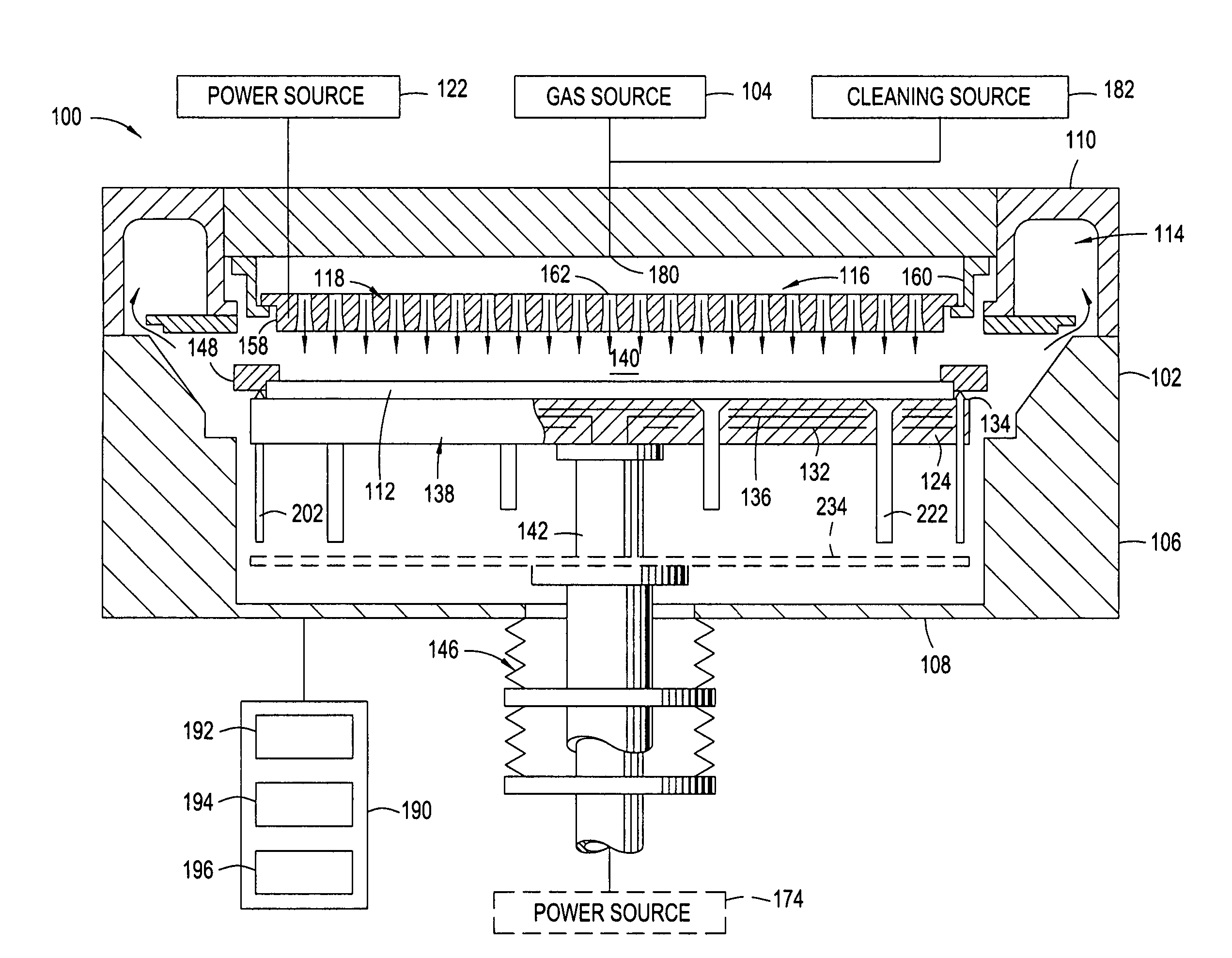
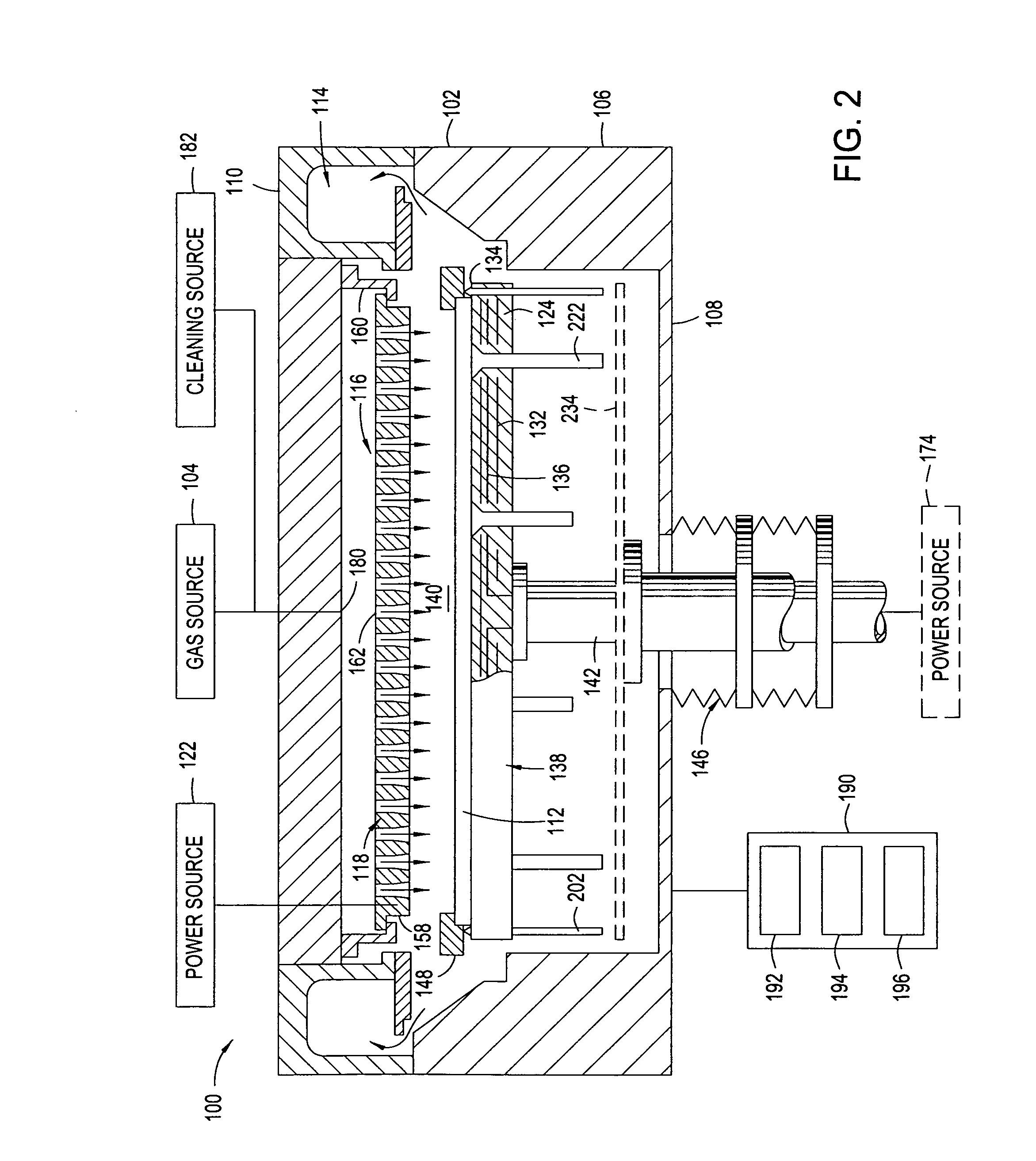
[0023] The invention provides a substrate support assembly and method for controlling the temperature of a substrate within a process chamber on a large area substrate. FIG. 2 illustrates an exemplary process chamber 100 according to one embodiment of the invention. The invention is illustratively described below in reference to a plasma enhanced chemical vapor deposition process chamber for processing large area substrates, such as those available from AKT, a division of Applied Materials, Inc., Santa Clara, Calif. However, it should be understood that the invention has utility in other system configurations such as physical vapor deposition systems, ion implant systems, etch systems, chemical vapor deposition systems, and any other system in which controlling the temperature of a substrate on a substrate support within a process chamber is desired.

[0024] The process chamber 100 includes a chamber body 102 having walls 106 and a bottom 108 that partially define a process volume 14...


PUM

PropertyMeasurementUnit
Temperatureaaaaaaaaaa

Abstract

A substrate support assembly and method for controlling the temperature of a substrate within a process chamber with a temperature uniformity of +/−5° C. are provided. A substrate support assembly includes a thermally conductive body comprising an aluminum material, a substrate support surface on the surface of the thermally conductive body and adapted to support the large area glass substrate thereon, one or more heating elements embedded within the thermally conductive body, and one or more cooling channels embedded within the thermally conductive body and positioned around the one or more heating elements. A process chamber comprising the substrate support assembly of the invention is also provided.

Description

BACKGROUND OF THE INVENTION [0001] 1. Field of the Invention [0002] Embodiments of the invention generally provide a substrate support utilized in flat panel substrate processing. [0003] 2. Description of the Related Art [0004] Liquid crystal displays or flat panel displays (FPD) are commonly used for active matrix displays such as computer and television monitors, personal digital assistants (PDAs), and cell phones, as well as solar cells and the like. Generally, a flat panel display comprises two glass plates having a layer of liquid crystal material sandwiched therebetween. At least one of the glass plates includes at least one conductive film disposed thereon that is coupled to a power supply. Power supplied to the conductive film from the power supply changes the orientation of the crystal material, creating a pattern such as texts or graphics on the flat panel displays. Substrates utilized for flat panel fabrication are large in size, often exceeding 300 mm ×400 mm, and are en...

Claims


Application Information

Patent Timeline
IPC IPC(8): F26B11/02H05B3/68C23C16/00
CPCC23C16/4586C23C16/463H01J37/32724H01J37/32715H01L21/67103C23C16/4583C23C16/4582C23C16/458H01L21/67069C23C16/46H01L21/683H01L21/687
Inventor LEUNG, SAMUELCHO, SU HOBAGLEY, WILLIAM ALLAN
Owner APPLIED MATERIALS INC
Why Eureka
Try Eureka