Electrical device cooling structure in vehicle

a technology of cooling structure and electric device, which is applied in the direction of electric propulsion mounting, electrochemical generator, chair, etc., can solve the problems of difficult to secure the cooling air passage when the seat is folded, and achieve the effect of effectively cooling an electrical device mounted, without reducing the foldability of the rear sea

Inactive Publication Date: 2007-02-22
HONDA MOTOR CO LTD
View PDF4 Cites 56 Cited by
  • Summary
  • Abstract
  • Description
  • Claims
  • Application Information

AI Technical Summary

Benefits of technology

[0007] Accordingly, it is an object of the present invention to effectively cool an electrical device mounted in the rear of a rear seat without reducing the foldability of the rear seat.

Problems solved by technology

However, Japanese Patent Application Laid-open No. 2004-1683 has a problem that because the intake duct for supplying the cooling air to the battery pack opens sideways of the seat back of the rear seat, the opening situates near an occupant's ear and generates nose.
However, in a vehicle provided with the diving-down foldable seat described in Japanese Patent Application Laid-open No. 2004-98722, it is difficult to secure a cooling-air passage when the seat is folded.

Method used


Image

  • Electrical device cooling structure in vehicle
  • Electrical device cooling structure in vehicle
  • Electrical device cooling structure in vehicle

Examples


first embodiment

[0046] The operation of the first embodiment having the above-described arrangement will be described below.

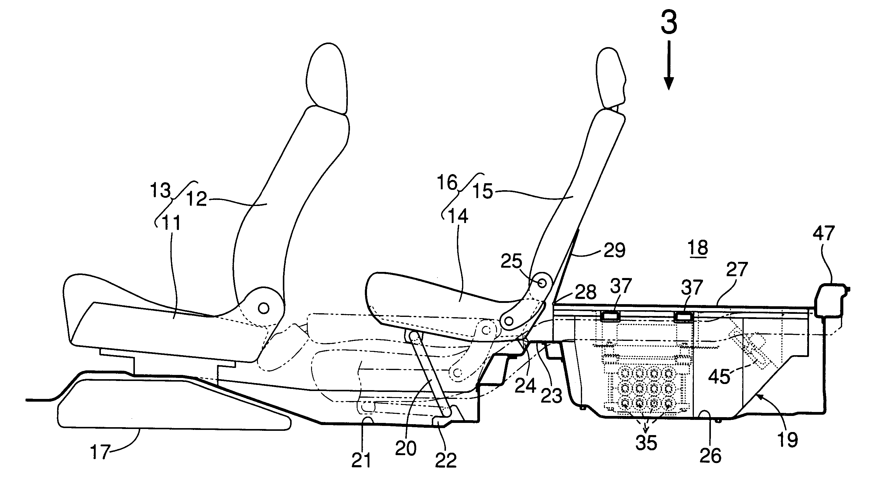
[0047] As shown in FIGS. 5, 6 and 9, when the rear seat 16 is in a use state, the cooling-air introduction port 34 between the lower case 31 and the upper case 32 of the power source unit 19 opens toward the rear end of the seat cushion 14. When the fans 45, 45 within the power source unit 19 are driven, conditioned cooling air existing in a space in front of the rear seat 16 is drawn rearward through a gap between the lower surface of the cooling-air introduction port 34 and the upper surface of the underseat floor 21, and flows through the cooling-air introduction port 34 into the lower case 31 and the upper case 32 of the power source unit 19. A portion of the cooling air cools the bundled battery modules 35 while flowing through gaps between the battery modules 35.

[0048] Heat generated by the motor control device 44 accommodated in the control-unit accommodating box 42 is...

second embodiment

[0052] the present invention will now be described with reference to FIGS. 13 and 14.

[0053] A cross member 49 interconnecting left and right side frames 39, 39 is laterally disposed in the rear of a seat cushion 14 of a rear seat 16 in a folded state. The cross member 49 is formed to have a box-shaped section including a portion of a bulging portion 23 of a floor, and openings 49a and 49b are formed in front and upper surfaces of the cross member 49. When the rear seat 16 is folded, a first cooling-air introduction passage P1 is narrowed in the rear of the seat cushion 14, but-cooling air is passed through the cross member 49 at such a narrowed portion, that is, the inside of the cross member 49 is used as the first cooling-air introduction passage P1, thereby enabling a smooth flowing of the cooling air to enhance the cooling effect.

[0054] Although the embodiments of the present invention have been described, various modifications in design may be made without departing from the s...


PUM

PropertyMeasurementUnit
heightaaaaaaaaaa
structureaaaaaaaaaa
rigidityaaaaaaaaaa

Abstract

A rear seat is foldable by moving downward a seat cushion and folding forward a seat back. A power source unit is disposed below a rear floor to the rear of the rear seat. When the rear seat is in an unfolded state, cooling air can be introduced from inside a vehicle compartment, through a space between a lower surface of the seat cushion and an upper surface of an underseat floor, into a cooling-air introduction port in the power source unit. When the rear seat is in a folded state, the cooling air is introduced from inside the vehicle compartment, through cooling-air introduction passages, into the cooling-air introduction port. Thus, the power source unit can be cooled irrespective of whether the rear seat is in the folded state, without reducing the foldability of the rear seat.

Description

RELATED APPLICATION DATA [0001] The Japanese priority application No. 2005-208041 upon which the present application is based is incorporated in its entirety herein by reference. BACKGROUND OF THE INVENTION [0002] 1. Field of the Invention [0003] The present invention relates to an electrical device cooling structure in a vehicle, in which an electrical device disposed under a rear floor to the rear of a foldable rear seat is cooled by cooling air introduced from inside a vehicle compartment. Description of the Related Art [0004] Japanese Patent Application Laid-open No. 2004-1683 discloses an electrical device cooling structure, in which a battery pack for driving a motor for driving an automobile is mounted in a luggage space to the rear of a rear seat, and an intake duct for supplying cooling air to the battery back opens sideways of a seat back of a rear seat. [0005] Japanese Patent Application Laid-open No. 2004-98722 discloses a so-called diving-down foldable seat, in which a ...

Claims


Application Information

Patent Timeline
Patent Type & Authority Applications(United States)
IPC IPC(8): B60N2/32B60N2/36A47C7/72B60K1/04B60K11/06B62D25/20H01M10/60H01M10/613H01M10/615H01M10/625H01M10/633H01M10/6557H01M10/6563
CPCB60K1/04B60K2001/005B60N2/3075B60N2/36B60N2002/363B60N2/3068
Inventor OHKUMA, KANAETAKEDOMI, HARUMIKOIKE, EIJIKAWATA, MASAO
Owner HONDA MOTOR CO LTD
Why Eureka
Try Eureka