Method and system for elliptical-based surveillance

Inactive Publication Date: 2007-02-22
OMNIPOL
View PDF92 Cites 60 Cited by
  • Summary
  • Abstract
  • Description
  • Claims
  • Application Information

AI Technical Summary

Benefits of technology

[0010] The present invention provides improved systems and methods for use as a standalone elliptical-based air traffic surveillance system and for use with multilateration surveillance systems. As a standalone system, the method and system of the present invention provides location and i...

Problems solved by technology

Expanding surveillance coverage requires adding sensors to an existing multilater...

Method used


Image

  • Method and system for elliptical-based surveillance
  • Method and system for elliptical-based surveillance
  • Method and system for elliptical-based surveillance

Examples


Embodiment Construction

[0026] The present invention is now described with reference to the accompanying Figures where like reference numbers denote like elements or steps.

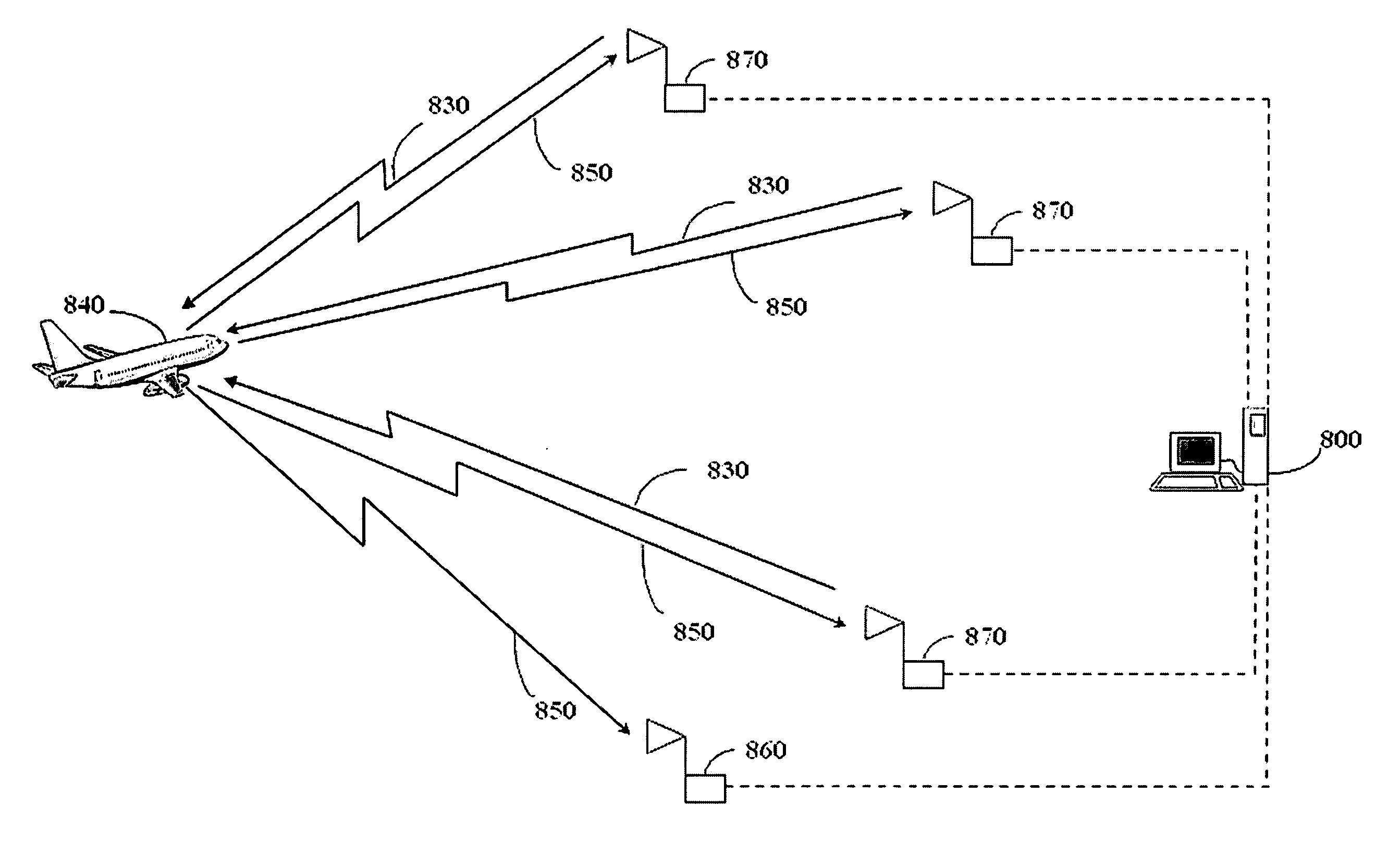
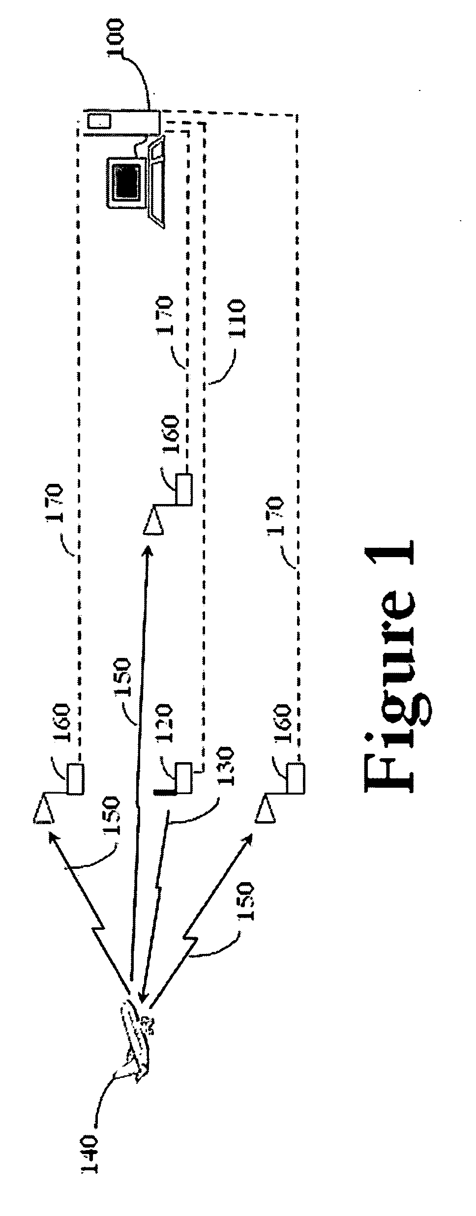
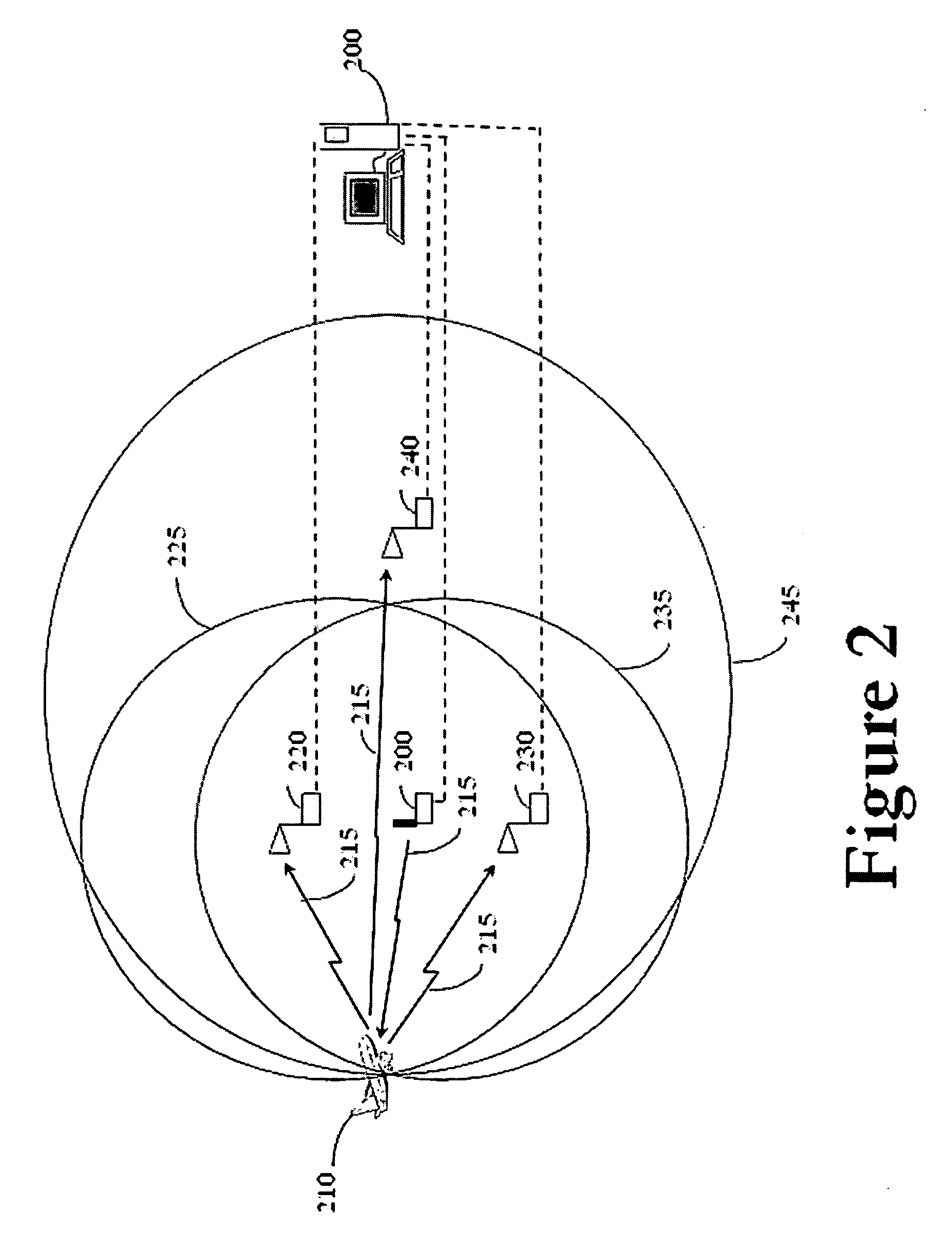
[0027] Referring to FIG. 1, in the preferred embodiment, an elliptical-based surveillance ground system comprising one or more 1090 MHz remote receivers 160, one or more 1030 MHz remote transmitters 120, and a central workstation 100 may be used to position and identification surveillance of one or more transponder-equipped aircraft 140. 1090 MHz remote receivers 160 and 1030 MHz remote transmitters 120 are time synchronized to a common high accuracy time reference source, such as Global Positioning System (GPS). 1090 MHz remote receiver 160 with associated antenna is separated in distance from 1030 MHz remote transmitters 120 with associated antenna.

[0028] One or more 1030 MHz remote transmitters 120 transmit a 1030 MHz interrogation 130 in accordance with the Minimum Operational Performance Standards For Traffic Alert And Collision A...


PUM


Abstract

A method and system are provided for performing elliptical-based and hybrid surveillance, performing false target detection and resolution, and performing integrity monitoring using one or more receiving and transmitting elements time synchronized to a common precision time reference, and a central workstation. Antennas for transmitting and receiving elements are located at known positions separated from one another. At a given time, one of the transmitting elements transmits an interrogation signal to one or more targets, which respond to the interrogation with a reply transmission, received by one or more receiving elements. The central workstation calculates each target's ellipse of position with respect to each receiving element, using the interrogator element time of interrogation measurement and each receiving element's time of arrival measurement for the corresponding reply transmission, and then fuses the elliptical line of positions for each receiving element to compute target positions or augment passive surveillance position. At a scheduled time, the one or more transmitting elements transmit a reference signal to the receiving elements(s). The central workstation uses each of the receiving elements time stamped signals to perform integrity monitoring.

Description

CROSS-REFERENCE TO RELATED APPLICATIONS [0001] This application is a Continuation-In-Part of U.S. patent application Ser. No. 11 / 343,079, Filed Jan. 30, 2006 and incorporated herein by reference; This application is also a Continuation-In-Part of U.S. patent application Ser. No. 11 / 342,289 filed Jan. 28, 2006 and incorporated herein by reference; This application is a Continuation-In-Part of U.S. patent application Ser. No. 11 / 203,823 filed Aug. 15, 2005 and incorporated herein by reference; This application is a Continuation-In-Part of U.S. patent application Ser. No. 1 / 145,170 filed on Jun. 6, 2006 and incorporated herein by reference; This application is a Continuation-In-Part of U.S. patent application Ser. No. 10 / 743,042 filed Dec. 23, 2003 and incorporated herein by reference; application Ser. No. 10 / 743,042 is a Continuation-In-Part of U.S. patent application Ser. No. 10 / 638,524 filed Aug. 12, 2003 and incorporated herein by reference; application Ser. No. 10 / 638,524 is a Con...

Claims


Application Information

Patent Timeline
IPC IPC(8): G01S13/08G01S3/02
CPCG01S7/003G01S13/878G01S2013/916
Inventor EVERS, CARL A.XIE, YUEBREEN, THOMAS J.
Owner OMNIPOL
Why Eureka
Try Eureka