Liquid container

a liquid container and liquid technology, applied in printing and other directions, can solve the problem of large size of ink cartridges, and achieve the effect of reducing size, high rigidity, and ensuring accuracy of positioning states

Active Publication Date: 2007-02-22
SEIKO EPSON CORP
View PDF4 Cites 16 Cited by
  • Summary
  • Abstract
  • Description
  • Claims
  • Application Information

AI Technical Summary

Benefits of technology

[0063] Further, since the individual connection mechanisms provided in the container mounting portion are disposed toward one side in the thicknesswise direction, the configuration of the container mounting portion can be reduced in size in the thicknesswise direction of the liquid container, and thus the liquid container and the container mounting portion can be reduced in size.
[0064] In the liquid container according to the second aspect of the invention, the two positioning portions are provided at both longitudinal edges of one surface of the container main body, that is, at positions having high rigidity close to the side wall of the container main body. For this reason, even though the torsional load or the pressure of the pressure chamber is applied to the container main body, displacement or deformation at both longitudinal ends of one surface of the container main body can be suppressed through firm fixing by the two positioning portions, and thus accurate positioning states can be kept. The displacement or deformation can be further suppressed by the liquid delivery portion, the pressurized fluid introduction portion, and the data storage unit provided between the two positioning portions. As a result, a stable connection state can be kept by accurate positioning states.

Problems solved by technology

Further, in the cartridge mounting portion, the parts corresponding to the connection mechanisms are provided, and thus the ink cartridge is likely to be large in size.

Method used


Image

  • Liquid container
  • Liquid container
  • Liquid container

Examples


Embodiment Construction

[0077] An embodiment of a liquid container according to the invention will now be described in detail with reference to the drawings.

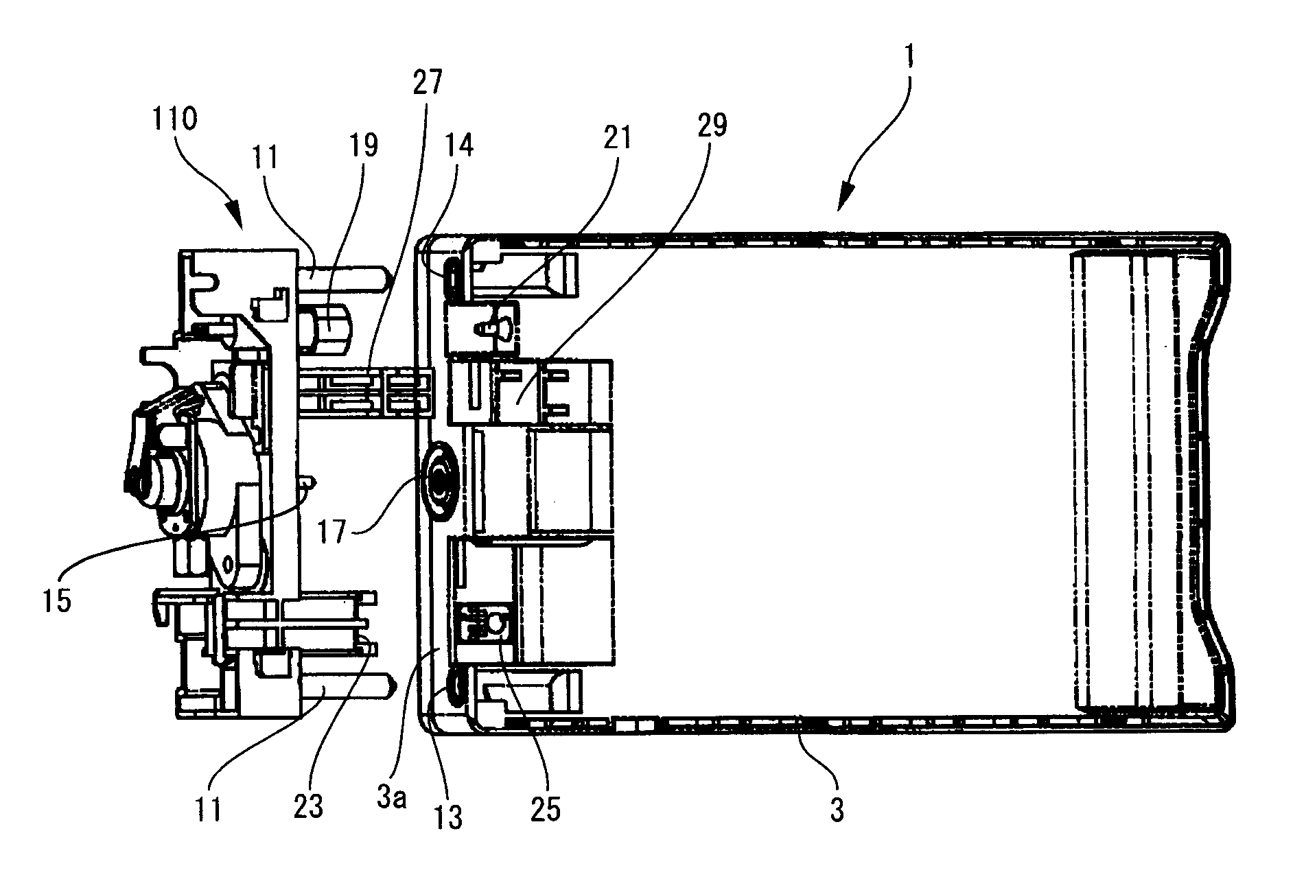
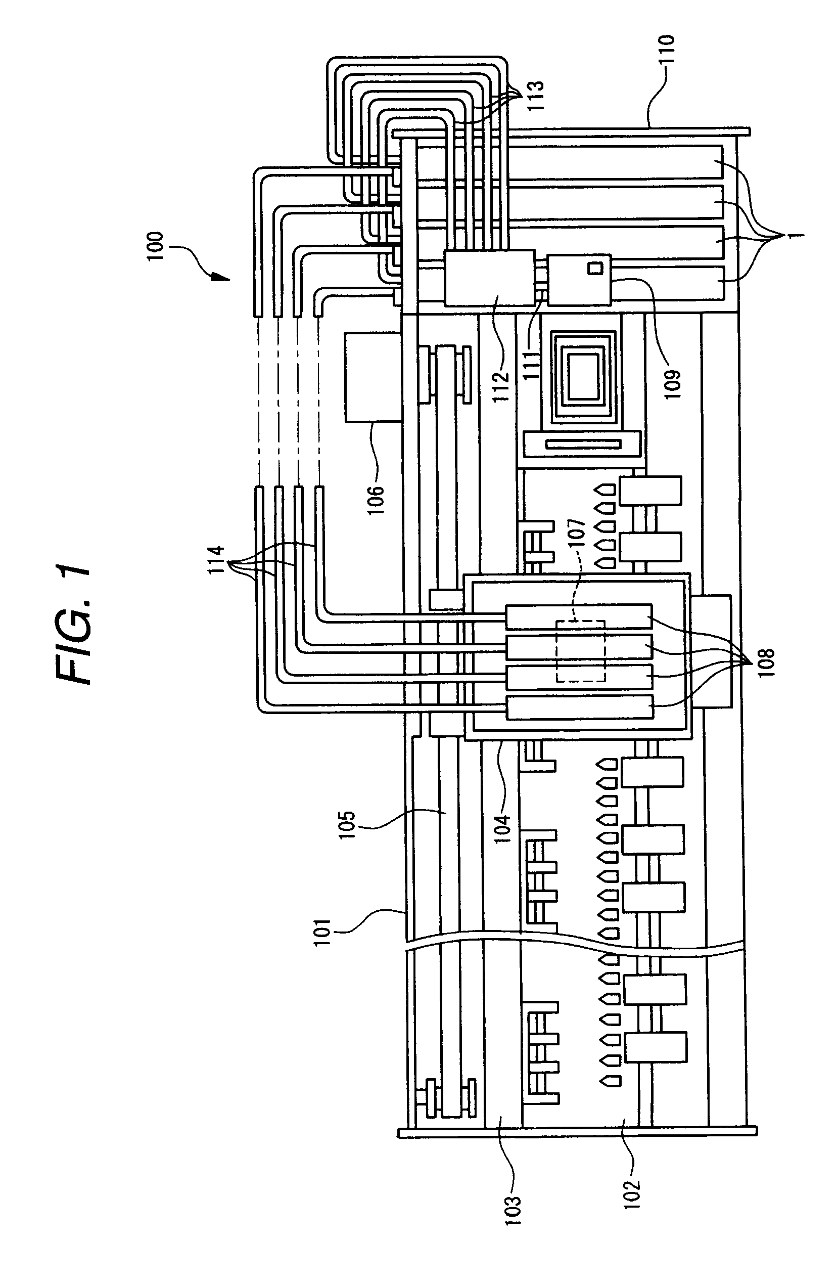
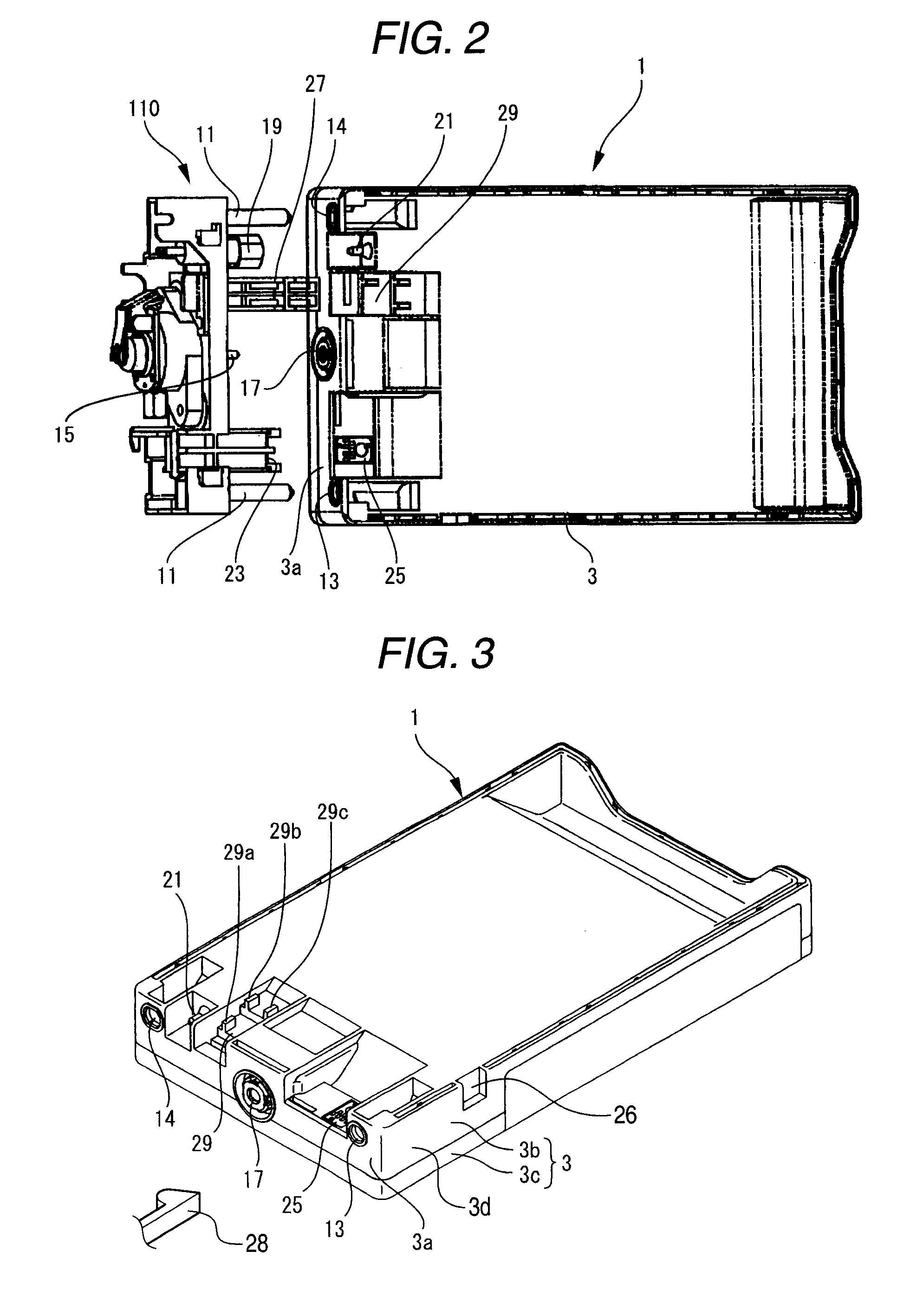
[0078]FIG. 1 is a plan view of an ink jet printer, on which an ink cartridge as a liquid container according to an embodiment of the invention is mounted. FIG. 2 is a perspective view of an ink cartridge and a cartridge mounting portion shown in FIG. 1. FIG. 3 is a perspective view of a single ink cartridge shown in FIG. 1. FIG. 4 is a left side view of an ink cartridge shown in FIG. 3. FIG. 5 is a front view of an ink cartridge shown in FIG. 3. FIG. 6 is a diagram showing the positional relationship of a left side view of an ink cartridge shown in FIG. 3 and a cartridge mounting portion on which the ink cartridge is mounted. FIG. 7 is an explanatory view of a connection state of an ink cartridge and a cartridge mounting portion shown in FIG. 6. FIG. 8 is a cross-sectional view taken along the line VIII-VIII of FIG. 7. FIG. 9 is a cross-sectional view...


PUM


Abstract

In an ink cartridge (liquid container) 1 of the invention, an ink delivery port 17 that connects an ink supply needle 15 of a cartridge holder 110 to an ink containing chamber 7 is disposed at an substantially central position in a shorter side direction of a container front surface 3a. Two positioning portions 13 and 14 that fit to positioning pins 11 provided at two places in the cartridge holder 110 so as to position a container main body 3, a pressurized air introduction portion 21 that connects a pressurized air supply path 19 of the cartridge holder 110 to a pressure chamber 5, and a data storage unit 25 that is connected to a connection terminal 23 of the cartridge holder 110 are disposed toward one side in a shorter side direction of the container front surface 3a with respect to the ink delivery port 17.

Description

BACKGROUND OF THE INVENTION [0001] 1. Technical Field of the Invention [0002] The present invention relates to a liquid container that contains a liquid to be supplied to a liquid jetting apparatus therein. [0003] 2. Description of the Related Art [0004] As a liquid container that contains a liquid to be used in a liquid jetting apparatus, for example, an ink cartridge that is used in an ink jet printer can be exemplified. The ink cartridge for an ink jet printer has an ink containing chamber that is provided in a container main body and contains ink to be supplied to a printing head. Upon use, the ink cartridge is detachably fitted into and mounted on a cartridge mounting portion located at a predetermined position. Then, ink contained in the ink containing chamber is supplied to the printing head that is driven according to printing data to be transmitted from a host computer, and then is jetted to a target position on a subject to be printed, such as a paper or the like, by nozzl...

Claims


Application Information

Patent Timeline
Patent Type & Authority Applications(United States)
IPC IPC(8): B41J2/175
CPCB41J2/17513B41J2/17523B41J2/17553B41J2/17546B41J2/17526B41J2/17506B41J2/17509B41J2/17559B41J2/17566B41J2/17596
Inventor MATSUMOTO, HITOSHI
Owner SEIKO EPSON CORP
Why Eureka
Try Eureka