Check patentability & draft patents in minutes with Patsnap Eureka AI!

Image sensing apparatus and image processing method

a technology of image sensing and image processing, which is applied in the field of image sensing apparatus, can solve the problems of non-uniformity of gradation on human face images, inability of display devices to satisfactorily display the effect of wide dynamic range, and failure of display devices such as monitors to secure wide dynamic range, so as to shorten processing time and eliminate the likelihood of contrast lowering

Inactive Publication Date: 2007-02-22
KONICA MINOLTA INC
View PDF6 Cites 79 Cited by
  • Summary
  • Abstract
  • Description
  • Claims
  • Application Information

AI Technical Summary

Benefits of technology

The present invention aims to provide an image sensing apparatus and an image processing method that can prevent the decrease in contrast of a main subject image during a processing process. The invention also aims to shorten the processing time. The image sensing apparatus includes an extractor for extracting a first component and a second component from a photographic image, a compressor for compressing the dynamic range of the first component with a predetermined ratio, an image generator for generating an image based on the compressed first component and the second component, and a level value setter for setting a level value for the first component. The compressor compresses the dynamic range of the first component in an area where its value is equal to or larger than the level value set by the level value setter. This invention can improve the quality of images and enhance the overall processing efficiency.

Problems solved by technology

In recent years, image sensing apparatuses such as digital cameras have a challenging task of providing an image sensor capable of enlarging a luminance range i.e. a dynamic range of a subject image to meet a demand for high-quality image reproduction.
Whereas a sensing device such as the linear-logarithmic sensor has succeeded in securing a wide dynamic range, a display device such as a monitor has not succeeded in securing a wide dynamic range, as compared with the sensing device.
Even if a wide dynamic range is obtained for an input image, the effect of the wide dynamic range cannot be satisfactorily exhibited on the display device.
Accordingly, there is likelihood that an illumination component of a main subject image i.e. a main subject luminance may be compressed, which leads, for example, to gradation non-uniformity on a human face image, which is a generally important part of a photo, e.g. appearance of a so-called “whiteout”, an overexposed appearance of a face image, which normally appears bright.
If, however, dodging is performed for a reflectance component in an area indicated by 922 where the pixel value is equal to or larger than the predetermined value θ, as mentioned above, there occurs a drawback that image I′>image I, which may degrade the S / N ratio.
In other words, unduly increase of brightness on a dark image area may increase a noise component, which may resultantly degrade the image quality.

Method used


Image

  • Image sensing apparatus and image processing method
  • Image sensing apparatus and image processing method
  • Image sensing apparatus and image processing method

Examples


first embodiment

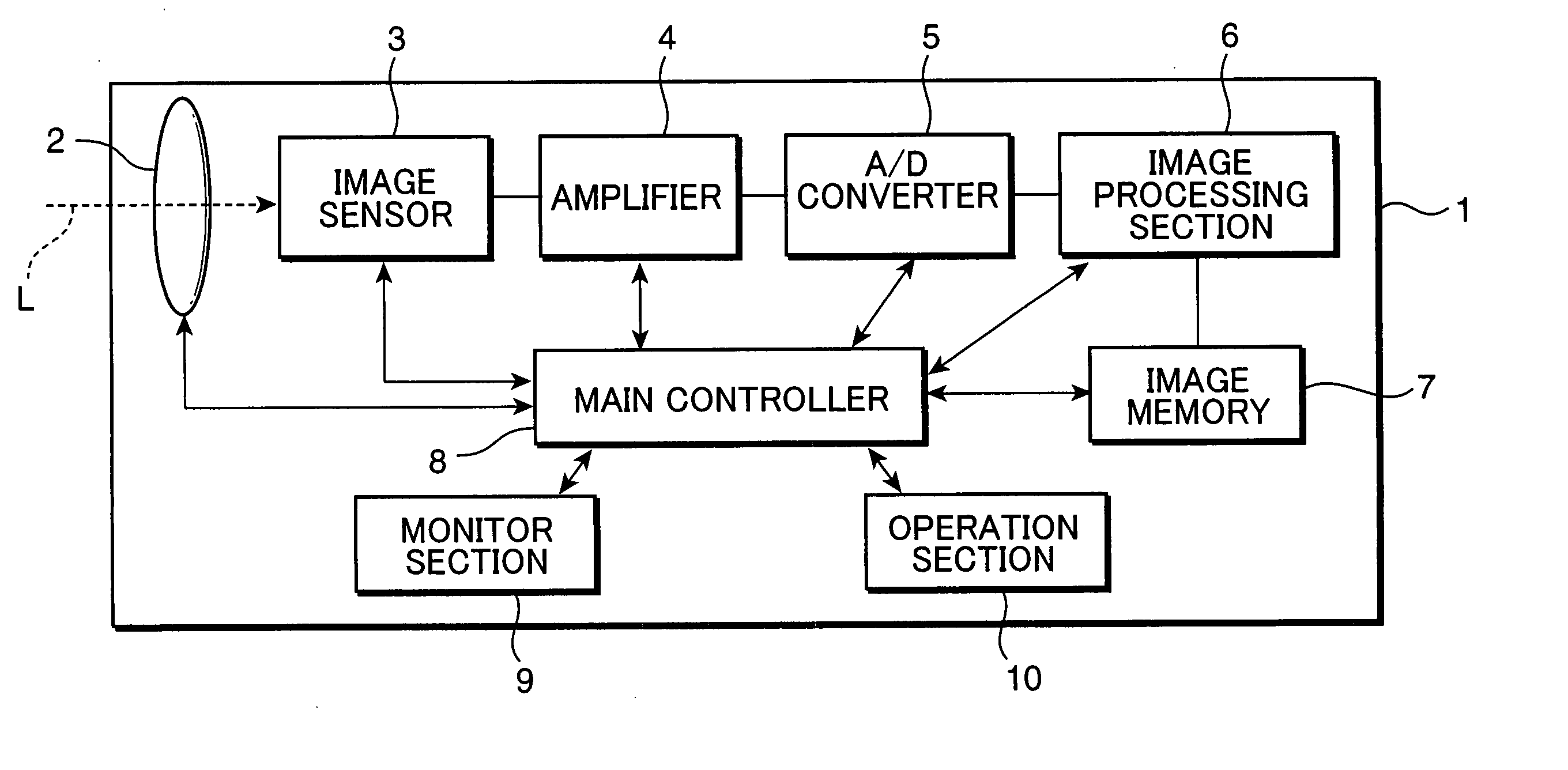
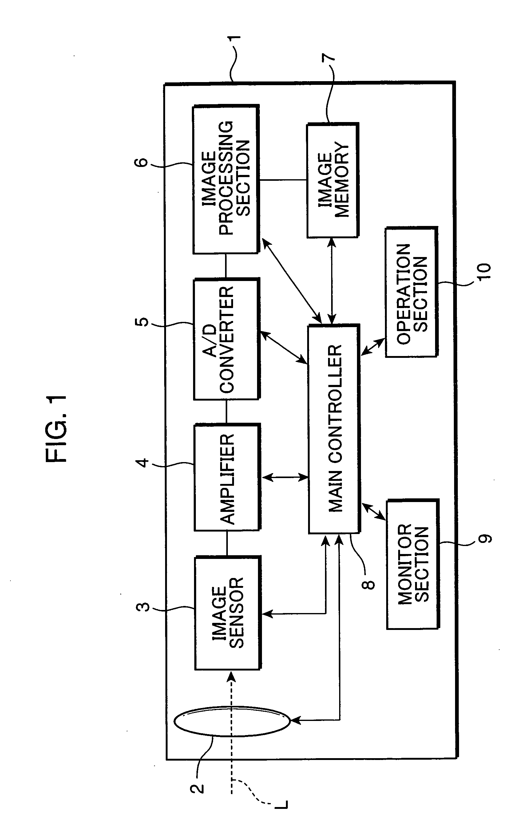
[0031]FIG. 1 is a block diagram schematically showing parts primarily relating to an image sensing process of a digital camera, which is an example of an image sensing apparatus according to a first embodiment of the invention. As shown in FIG. 1, the digital camera 1 includes a lens unit 2, an image sensor 3, an amplifier 4, an analog-to-digital converter (A / D converter) 5, an image processing section 6, an image memory 7, a main controller 8, a monitor section 9, and an operation section 10.

[0032] The lens unit 2 functions as a lens aperture for receiving light representing a subject image i.e. a light image, and includes an optical lens system for guiding the light image toward the image sensor 3 disposed inside a camera body. The optical lens system includes, for instance, zoom lens elements arrayed in series along an optical axis L of the light image, a focusing lens element, and other fixed lens block. The lens unit 2 has a diaphragm (not shown) for regulating the amount of l...

second embodiment

[0059] The digital camera 1 in the first embodiment uses the edge keeping filter to extract the illumination component “L”. In view of a point that it takes a time to perform the illumination component extraction using the edge keeping filter, a digital camera 1a in a second embodiment of the invention adopts a technique that a provisional illumination component image (hereinafter, called as “provisional illumination image”) is obtained prior to the illumination component extraction, and a dodging processing is performed based on the provisional illumination image. The dodging processing in the second embodiment is performed as follows.

[0060]FIG. 5 is a block diagram showing functional parts of an image processing section 6a in the digital camera 1a. As shown in FIG. 5, the image processing section 6a includes a provisional image creator 68 and an illumination component extraction area calculator 69, in addition to functional parts corresponding to the functional parts of the image...

third embodiment

[0065] Referring back to FIG. 16, according to the conventional dodging processing, the linear-logarithmic image obtained by the linear-logarithmic sensor is divided into the logarithmic image “I1” and the linear image “I2” for extraction, the dodging processing is performed for the respective images, and the processed images are synthesized. The synthesized image is shown by the image “I′” in FIG. 17. Dynamic range compression is performed for the original image “I” as the input image i.e. the linear-logarithmic image so that the synthesized image “I′” has a dynamic range of the output image on a display device such as a monitor.

[0066] In the conventional dodging processing, if the original image “I” includes a subject image e.g. an image of clouds having a large reflectance in a high luminance area, the synthesized image “I′” may have an output value over the dynamic range of the output image, which may lead to contrast lowering. Specifically, as shown in FIG. 20, for instance, a...


PUM


Abstract

An image sensing apparatus includes: an image sensing device for sensing light representing a subject image; a first component extractor for extracting a first component having a predetermined frequency out of a photographic image obtained by the image sensing device; a second component extractor for extracting a second component having a frequency higher than the frequency of the first component out of the photographic image; a compressor for compressing a dynamic range of the first component extracted by the first component extractor with a predetermined compression ratio; an image generator for generating an image based on a compressed first component obtained by compressing the dynamic range of the first component by the compressor, and the second component extracted by the second component extractor; and a compression correction coefficient calculator for calculating a compression correction coefficient used in compressing the first component, using the second component extracted by the second component extractor, wherein the compressor determines the compression ratio in such a manner that the larger compression correction coefficient increases the compression ratio based on the compression correction coefficient calculated by the compression correction coefficient calculator, and compresses the dynamic range of the first component based on the determined compression ratio.

Description

[0001] This application is based on Japanese Patent Application No. 2005-235987, No. 2005-235988, No. 2006-131740, and No. 2006-131741 filed on Aug. 16, 2005, Aug. 16, 2005, May 10, 2006, and May 10, 2006, respectively, the contents of which are hereby incorporated by reference. BACKGROUND OF THE INVENTION [0002] 1. Field of the Invention [0003] The present invention relates to an image sensing apparatus such as a digital camera, and more particularly to an image sensing apparatus having a dynamic range compression function, and an image processing method adapted to the image sensing apparatus. [0004] 2. Description of the Related Art [0005] In recent years, image sensing apparatuses such as digital cameras have a challenging task of providing an image sensor capable of enlarging a luminance range i.e. a dynamic range of a subject image to meet a demand for high-quality image reproduction. Concerning a technique on the dynamic range enlargement, there is known an image sensor having...

Claims


Application Information

Patent Timeline
Patent Type & Authority Applications(United States)
IPC IPC(8): H04N5/235H04N23/40
CPCH04N5/243H04N23/76
Inventor KATAGIRI, TETSUYAKAMON, KOICHI
Owner KONICA MINOLTA INC
Features
  • R&D
  • Intellectual Property
  • Life Sciences
  • Materials
  • Tech Scout
  • Unparalleled Data Quality
  • Higher Quality Content
  • 60% Fewer Hallucinations
Learn More