
Apparatus for converting image signal and a method thereof

a technology of image signal and apparatus, applied in the direction of signal generator with optical-mechanical scanning, selective content distribution, television systems, etc., can solve the problem of constant speed deterioration of picture quality of characters and graphics, and achieve the effect of enhancing picture quality

Inactive Publication Date: 2007-02-22
SAMSUNG ELECTRONICS CO LTD
View PDF8 Cites 28 Cited by
  • Summary
  • Abstract
  • Description
  • Claims
  • Application Information

AI Technical Summary

Benefits of technology

The present invention provides an apparatus and method for converting image signals by applying interpolation differently based on characters and graphics moving with a constant speed and direction in an image. This enhances picture quality by improving the motion estimation and analysis of the image. The apparatus includes a motion estimation unit, a ticker region detection unit, a motion information analysis unit, and an interpolation unit. The motion information analysis unit determines whether or not there is an image moving with a constant speed and direction in the ticker region and controls the degree of temporal and spatial interpolation accordingly. The interpolation unit interpolates the current field by controlling the degree of temporal and spatial interpolation using an output of the motion information analysis unit. The technical effect of the invention is to improve the quality of images by enhancing the motion estimation and analysis of the image.

Problems solved by technology

As a result, there is a disadvantage in that the picture quality of characters and graphics moving at a constant speed is deteriorated due to uses of the intra-field interpolation pixels for characters and graphics moving at a constant speed.

Method used


Image

  • Apparatus for converting image signal and a method thereof
  • Apparatus for converting image signal and a method thereof
  • Apparatus for converting image signal and a method thereof

Examples


Embodiment Construction

[0029] Certain exemplary embodiments of the present invention will be described in greater detail with reference to the accompanying drawings.

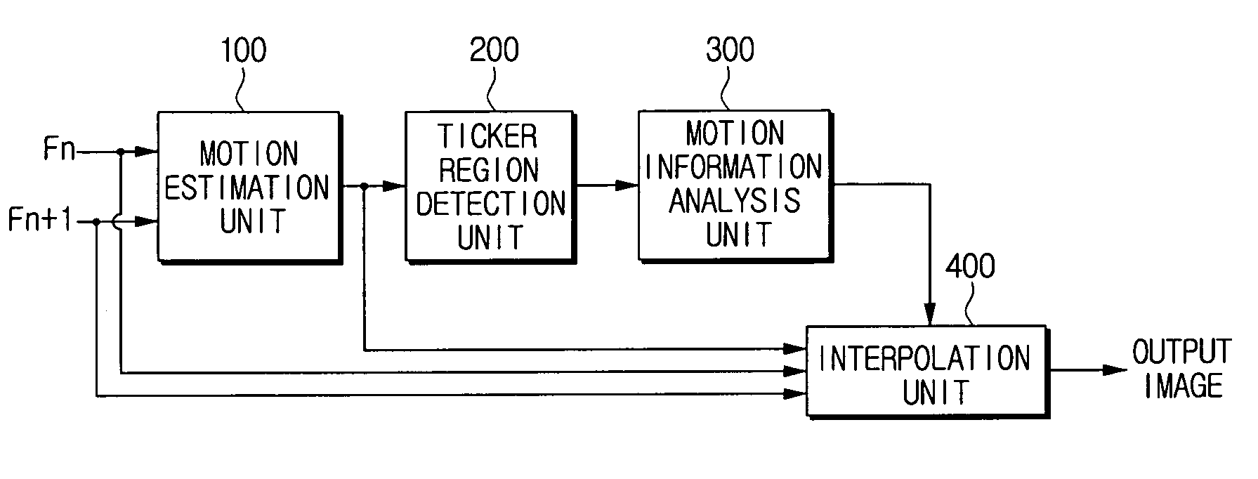
[0030]FIG. 1 is a block diagram illustrating an apparatus for converting an image signal according to one exemplary embodiment of the present invention.

[0031] Referring to FIG. 1, the apparatus for converting an image signal of the present invention includes a motion estimation unit 100, a ticker region detection unit 200, a motion information analysis unit 300 and an interpolation unit 400.

[0032] First, the motion estimator unit 100 estimates a motion vector indicating a direction and magnitude of motion using a current field and a reference field. At this time, the reference field can be a previous field consecutively input before the current field or a next field consecutively input after the current field. Also, motion estimation can be calculated by calculating motion vectors not only between temporally consecutive fields but also betw...


PUM


Abstract

An apparatus for converting an image signal includes a motion estimation unit which estimates a motion vector using current and reference fields; a ticker region detection unit which detects a ticker region of an image using the estimated motion vector where an image moving with a constant speed and direction in a current field is found; a motion information analysis unit which determines whether or not there exists an image moving with a constant speed and direction in the ticker region based on the frequency of a motion vector estimated within the detected ticker region; and an interpolation unit which interpolates the current field by controlling a degree of temporal and spatial interpolations using an output of the motion information analysis unit. Accordingly, interpolation is differently applied in accordance with characters and graphics moving with a constant speed and direction in an input image, so that picture quality can be enhanced.

Description

[0001] This application claims priority under 35 U.S.C. § 119 from Korean Patent Application No. 10-2005-0075443, filed on Aug. 17, 2005, the entire content of which is incorporated herein by reference. BACKGROUND OF THE INVENTION [0002] 1. Field of the Invention [0003] Apparatuses and methods consistent with the present invention relate to converting an image signal and a method thereof, and more particularly to an apparatus for converting an image signal and a method thereof, which detect texts and graphics being contained in an image signal and moving in a fixed direction, and implement interpolation based thereon. [0004] 2. Description of the Related Art [0005] An interlace scan mode and a progressive scan mode are provided as scan modes of an image display apparatus. The interlace scan mode is used for general TVs and the like. The interlace scan mode is a mode that, when one image is displayed, divides one image frame into two fields and sequentially and alternately displays t...

Claims


Application Information

Patent Timeline
Patent Type & Authority Applications(United States)
IPC IPC(8): H04N7/01
CPCH04N5/145H04N7/012H04N7/0137H04N7/014H04N21/4884H04N7/01
Inventor LEE, YOUNG-HOYANG, SEUNG-JOON
Owner SAMSUNG ELECTRONICS CO LTD
Learn More