Head for thermally assisted magnetic recording device and thermally assisted magnetic recording device

Inactive Publication Date: 2007-02-22
HITACHI LTD
View PDF8 Cites 36 Cited by
  • Summary
  • Abstract
  • Description
  • Claims
  • Application Information

AI Technical Summary

Benefits of technology

[0010] It is preferable that the direction of polarization of the light, which is made incident on the above-described configuration, is set parallel to a slit of a portion where the leader lines are attached. By this, an amount of light leaking from the leader line portion can be redu

Problems solved by technology

In a conventional magnetic recording device, there is a problem that recorded information is lost due to thermal fluctuations when a recording density becomes not less than 1 Tn/in2.
However, since the intensity of a magnetic field which can be generated is limited in size, it becomes impossible to form a

Method used


Image

  • Head for thermally assisted magnetic recording device and thermally assisted magnetic recording device
  • Head for thermally assisted magnetic recording device and thermally assisted magnetic recording device
  • Head for thermally assisted magnetic recording device and thermally assisted magnetic recording device

Examples


Example

First Embodiment

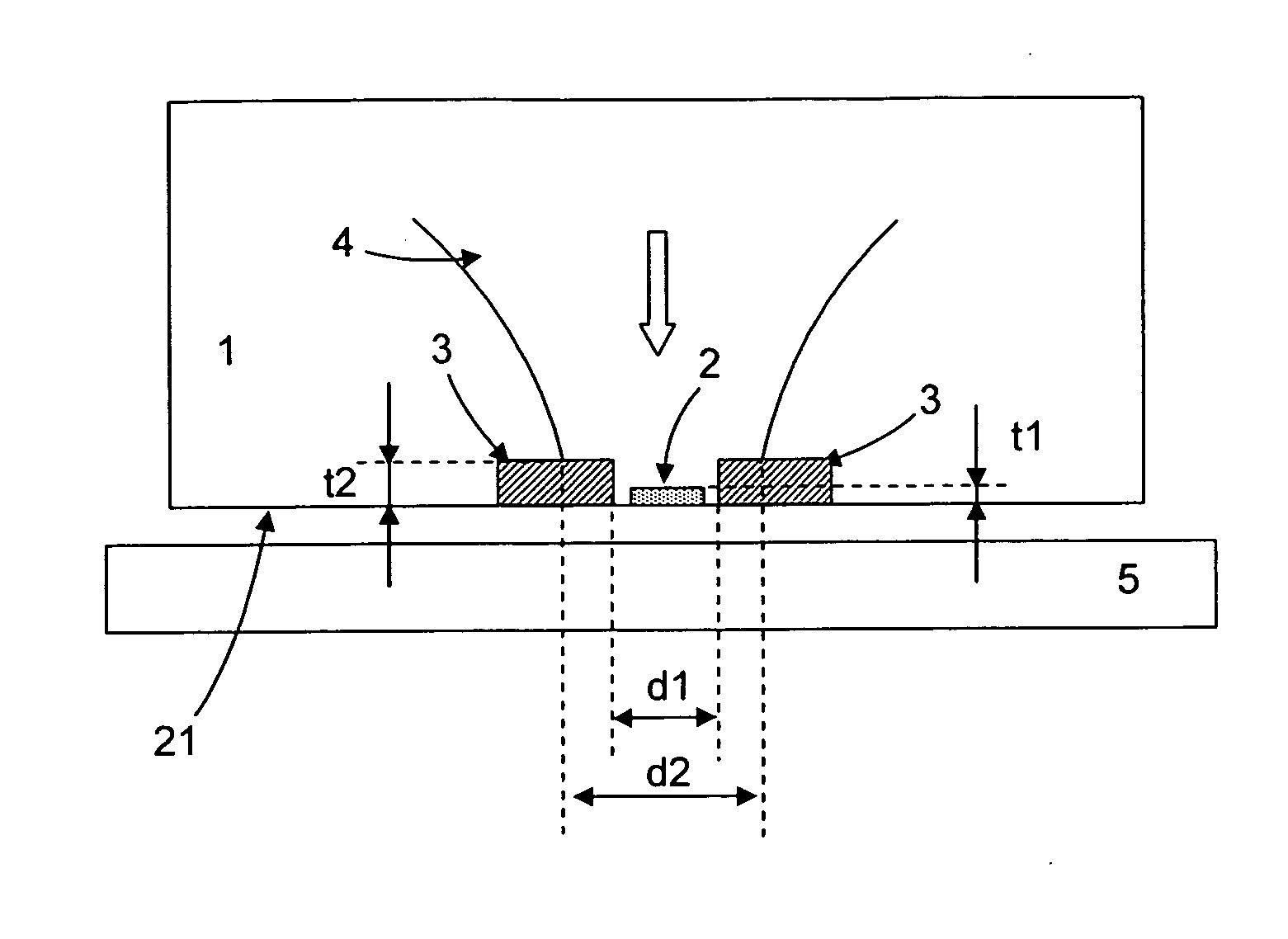
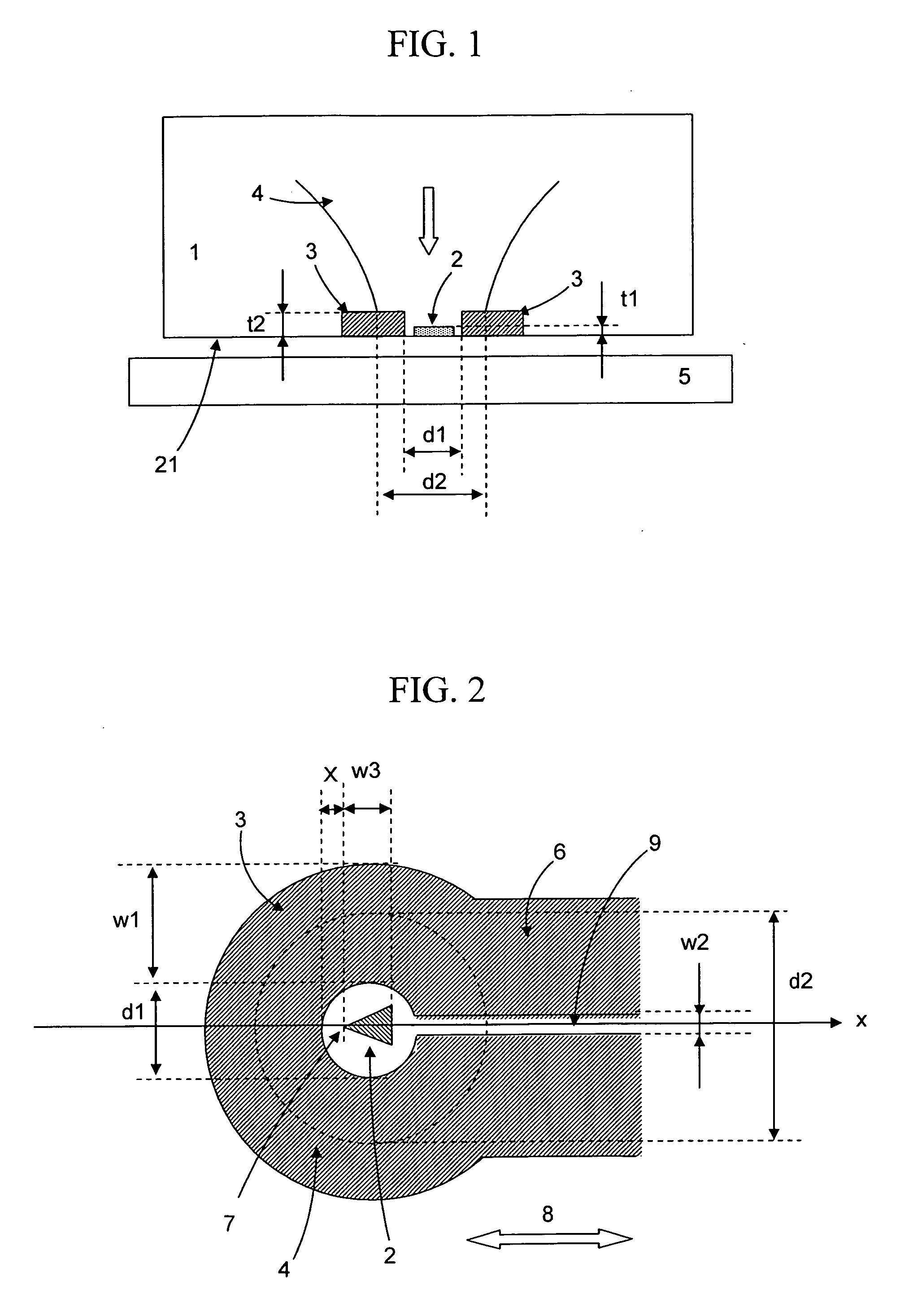
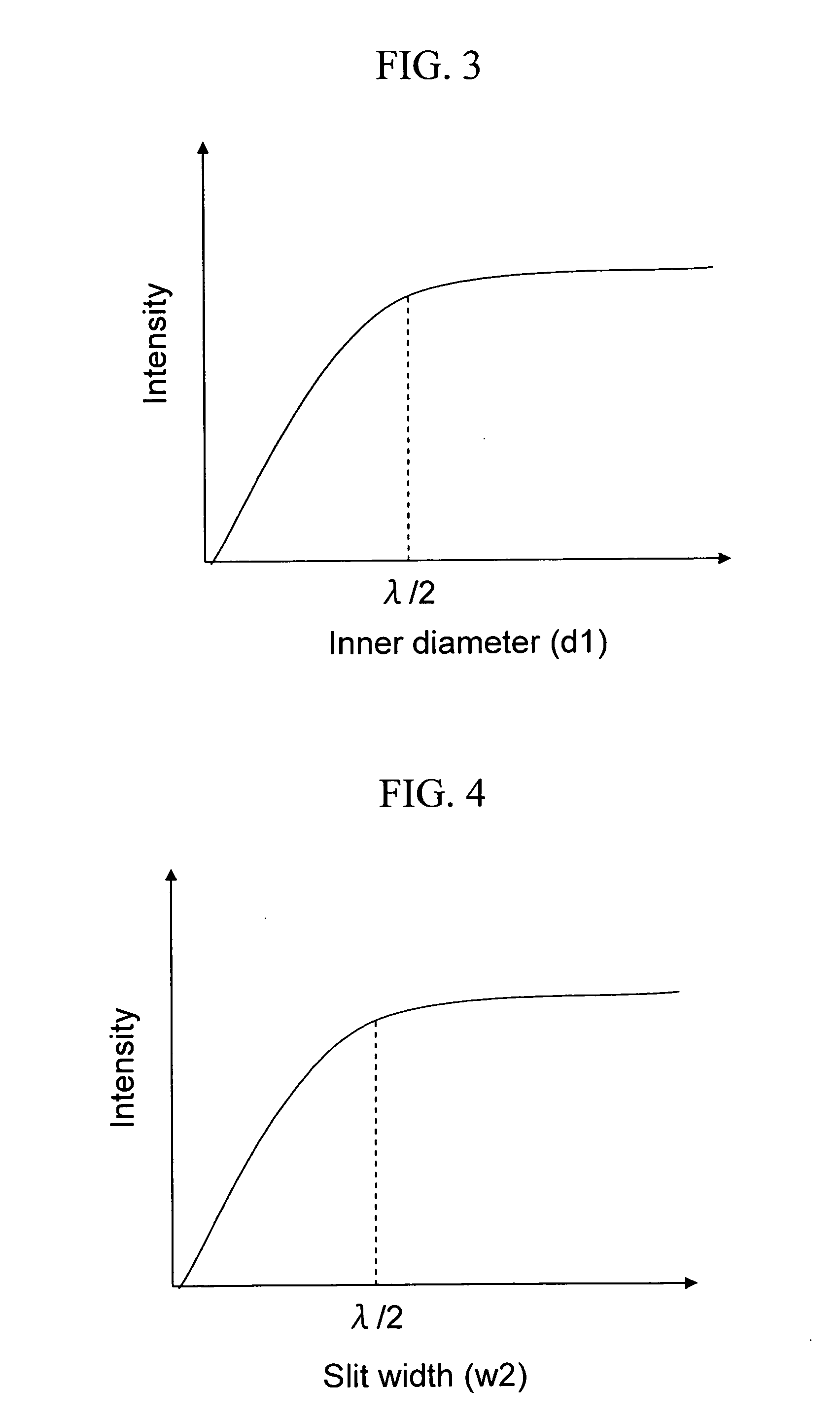
[0044] In a head for a thermally assisted magnetic recording device of the present invention, as shown in FIG. 1, a circular coil 3 is placed on a bottom portion of a slider 1 to be a main body of the head, and a scatterer 2 having conductivity for generating an optical near-field is placed in the center of the coil. Incident light 4 is made incident from an upper side of the coil 3. Here, the upper side means a side which is opposed to a side where a medium 5 is placed. In this case, a width d1 of the inside of the coil 3 is not larger than a spot diameter (d2) of the incident light 4, that is, not larger than the wavelength of the incident light. Accordingly, the background light generated in the circumference of an optical near-field generating element (a scatterer) 2 is eliminated. Here, the width of the inside of the coil means a width of the smallest portion of widths out of spaces opened in the coil center.

[0045] In the present embodiment, the slider 1, whos...

Example

Second Embodiment

[0052] Next, an embodiment in a case where a width of the inside of the coil is varied in an upper side and a lower side will be described. In the above-described configuration, to improve utilization efficiency of light energy, as shown in FIG. 6, a width d3 of the inside of the coil in the upper side of the coil (the side where the light is made incident) is made larger than a width d1 of the inside of the coil in the lower side of the coil (the side where the light goes out). By doing so, a component of the incident light 4, which reflects without entering a hollow portion in the inside of the coil, becomes smaller, so that the light utilization efficiency is improved. In addition, as shown in FIG. 6, when a wall of the inside portion of the coil is tilted, the light irradiating the wall is reflected and concentrated in the center portion, so that energy density of the light incident on the metal scatterer 2 can be increased. That is, the coil 3 can be caused to...

Example

Third Embodiment

[0055] Next, an embodiment in a case where the base of the coil is apart from the base of the slider will be described.

[0056] The base of the coil 3 is not necessarily on a level with the base of the slider. As shown in FIG. 8, the coil may be placed so that a distance between the base of the coil 3 and a surface of the medium 5 becomes larger than a distance between an air bearing surface of the slider and the surface of the medium 5. In general, in a vicinity of an edge of a circular aperture, intensified scattered light (localized light) is generated, but similar scattered light is also generated in the vicinity of an edge 14 of the coil 3, which functions as a shading film. When the scattered light is absorbed in the medium, it causes expansion of a heating region. In contrast, as in the case of the above-described configuration, the base of the coil 3 is placed apart from the medium, so that the scattered light generated in the edge 14 becomes difficult to be ...


PUM


Abstract

To reduce background light generated in a circumference of a scatterer in a head for a thermally assisted magnetic recording device using a scatterer having conductivity as an optical near-field generating element, a coil for generating a magnetic field is placed on a bottom portion of a slider, and an optical near-field generating element is placed in an inside of the coil. At this time, an inner diameter of the coil is set not larger than a wavelength of incident light, an interval between leader lines each for conducting an electric current to the coil is set not larger than a half of the wavelength of the light, and the coil for generating the magnetic field is caused to function as a shield for suppressing the background light.

Description

CLAIM OF PRIORITY [0001] The present application claims priority from Japanese application JP 2005-238908 filed on Aug. 19, 2005, the contents of which is hereby incorporated by reference into this application. BACKGROUND OF THE INVENTION [0002] 1. Field of the Invention [0003] The present invention relates to a head for a thermally assisted magnetic recording device and a thermally assisted magnetic recording device. [0004] 2. Description of the Related Art [0005] Recently, there has been proposed a thermally assisted magnetic recording method as a recording method achieving a recording density of not less than 1 Tn / in2 (H. Saga, H. Nemoto, H. Sukeda, and M. Takahashi [1999], “J. Appl. Phys”. 38, Part 1, 1839, Japan). In a conventional magnetic recording device, there is a problem that recorded information is lost due to thermal fluctuations when a recording density becomes not less than 1 Tn / in2. To prevent this, it is necessary to increase coercivity of a medium. However, since t...

Claims


Application Information

Patent Timeline
IPC IPC(8): G11B5/02
CPCG11B5/02G11B5/314G11B7/1387G11B11/10536G11B11/10554G11B2005/0002G11B2005/0021
Inventor MATSUMOTO, TAKUYANAKAMURA, KIMIOTAKAHASHI, YOSHIO
Owner HITACHI LTD
Why Eureka
Try Eureka