Correlation servo for positioning recording head

a technology of correlation servo and recording head, which is applied in the direction of maintaining head carrier alignment, digital recording, instruments, etc., can solve the problems of static shift, unstable ltm, and increased risk of errors, and achieve the effect of minimizing errors

Inactive Publication Date: 2007-02-22
QUANTUM CORP
View PDF21 Cites 22 Cited by
  • Summary
  • Abstract
  • Description
  • Claims
  • Application Information

AI Technical Summary

Benefits of technology

[0020] In another embodiment, a tape head cluster includes first and second servo heads and at least one data head for accessing data in a data band. The at least one data head is laterally positioned between the first and second servo heads, and each servo head includes at least three read elements for servoing off servo tracks in respective first and second servo bands. An associated controller includes position determination logic for determining, for each servo head, (a) a first parameter corresponding to the similarity between data read by a first pair of read elements in the servo head, (b) a second parameter corresponding to the similarity between data read by a second pair of read elements in the servo head, the second pair having one read element in common with the first pair, and (c) first and second positions of the respective first and second servo heads based upon a relationship between the first and second parameters. The controller also includes position control logic for adjust the head cluster to a lateral position based upon the first and second positions. The position control logic may adjust the head cluster to a lateral position that minimizes the errors experienced by the first and second servo heads.

Problems solved by technology

The tape therefore becomes more susceptible to errors caused from the tape shifting up or down (called lateral tape motion or “LTM”) in a direction perpendicular to the tape travel path as the tape passes by the magnetic head.
Some may cause abrupt momentary jumps while others may cause a static shift.
Generally, LTM is unpredictable and unrepeatable.
In multi-head, multi-channel magnetic tape storage systems, random lateral tape motion is generally a limiting factor in achieving higher track densities and thus higher user data capacity per tape.
Mis-registration between the head and data tracks can cause data errors during readback and data loss on adjacent tracks during writing.

Method used


Image

  • Correlation servo for positioning recording head
  • Correlation servo for positioning recording head
  • Correlation servo for positioning recording head

Examples


Embodiment Construction

[0030] The following description is presented to enable a person of ordinary skill in the art to make and use the invention. Descriptions of specific devices, techniques, and applications are provided only as examples. Various modifications to the examples described herein will be readily apparent to those of ordinary skill in the art, and the general principles defined herein may be applied to other examples and applications without departing from the spirit and scope of the invention. Thus, the present invention is not intended to be limited to the examples described herein and shown, but is to be accorded the scope consistent with the claims.

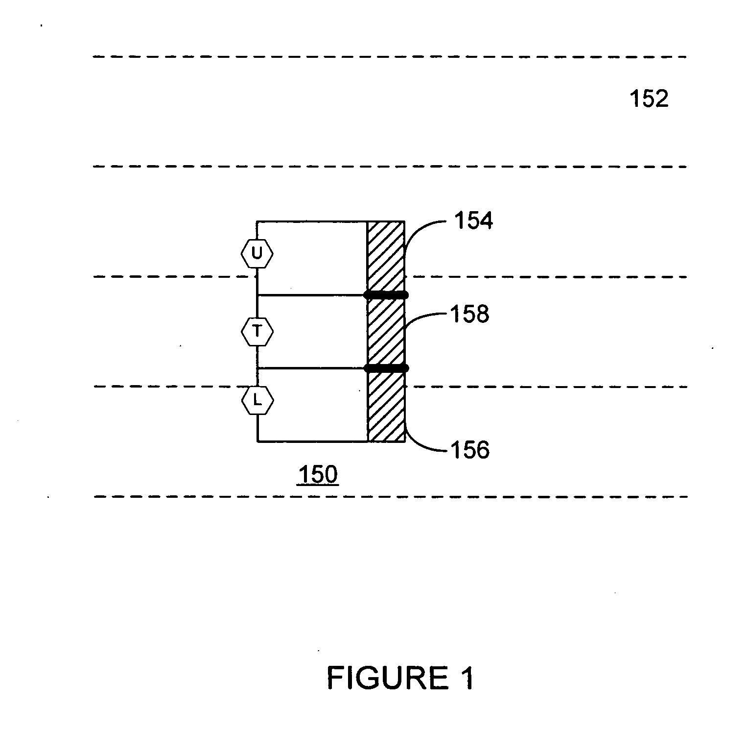
[0031]FIG. 1 illustrates a multi-tapped three-segment reader (MTR) 150 adjacent to data tracks on a magnetic medium 152 according to embodiments of the present invention. The edges of the data tracks are indicated by dashed lines and the three segments of the MTR are shown as hashed areas. Each segment is connected by wires, indicated by sol...


PUM

PropertyMeasurementUnit
distanceaaaaaaaaaa
distanceaaaaaaaaaa
widthaaaaaaaaaa

Abstract

Tape heads and controllers for controlling such heads in a tape drive are described. A controller may determine a first parameter corresponding to the similarity between data read by a first pair of read elements of a head, a second parameter corresponding to the similarity between data read by another pair of read elements having one read element in common with the first pair, and a position of the head with respect to a data track based upon a relationship between the first and second parameters. The controller may adjust the head to a proper lateral position based upon the determined position.

Description

BACKGROUND OF THE INVENTION [0001] 1. Field of the Invention [0002] The present invention generally relates to storage devices, and more particularly to servo systems for compensating for lateral tape motion. [0003] 2. Related Art [0004] Increased data storage capacity, and retrieval performance, are desired of all commercially viable mass storage devices and media. In the case of linear tape recording a popular trend is toward multi-head, multi-channel head structures with narrowed recording gaps and data track widths, so that many linear data tracks may be achieved on a tape medium of a predetermined width, such as one-half inch width tape. To increase the storage density for a given cartridge size the bits on the tape may be written to smaller areas and on a plurality of parallel longitudinal tracks. As more data tracks are recorded on a tape, each track becomes increasingly narrow. The tape therefore becomes more susceptible to errors caused from the tape shifting up or down (ca...

Claims


Application Information

Patent Timeline
Patent Type & Authority Applications(United States)
IPC IPC(8): G11B5/584G11B5/09G11B21/02
CPCG11B5/0083G11B5/49G11B5/584
Inventor NEUMANN, LAWRENCE G.
Owner QUANTUM CORP
Why Eureka
Try Eureka