Method for determining the position of a slider in an electromechanical valve

a technology of electromechanical valves and sliders, applied in the direction of magnets, magnets, instruments, etc., can solve the problems of distinctly increased costs, and achieve the effect of simple and favourably priced

Inactive Publication Date: 2007-02-22
TRW AUTOMOTIVE GMBH
View PDF4 Cites 12 Cited by
  • Summary
  • Abstract
  • Description
  • Claims
  • Application Information

AI Technical Summary

Benefits of technology

[0004] It is an object of the invention to provide a simple and favourably priced method for determining the position of a slider in an electromechanical valve.

Problems solved by technology

However, determining the position of the slider by means of a sensor requires additional expenditure with regard to components and additional structural measures which lead to distinctly increased costs.

Method used


Image

  • Method for determining the position of a slider in an electromechanical valve
  • Method for determining the position of a slider in an electromechanical valve

Examples


Embodiment Construction

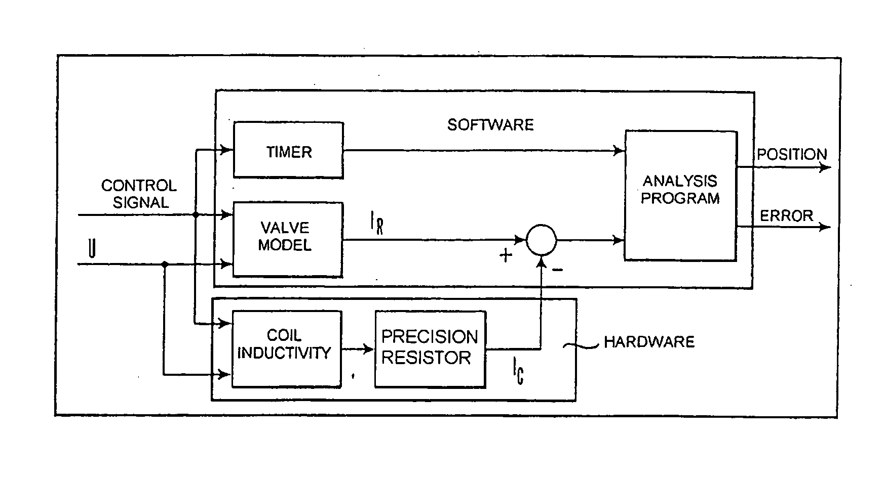
[0014] The process steps according to the invention for determining the position of a slider in an electromechanical valve can be seen from FIG. 1. A voltage U is applied to the slider, which is provided with a coil. The value of the voltage U is also supplied as an input quantity to a comparator program. The time-dependent current flow IC through the coil is measured by means of a precision resistor. The start of measurement is established by switching on a control signal which simultaneously activates the movement of the slider.

[0015] The measured current flow IC is automatically compared with reference values IR of a valve model by means of a computer program. The reference values may either be based on a hypothetical sample valve or may be obtained by one or more reference measurements with real sample valves. The measured values IC are subtracted from the reference values IR (or vice versa). The reference values IR are stored in a memory. It is established by means of an analy...


PUM

PropertyMeasurementUnit
current flowaaaaaaaaaa
timeaaaaaaaaaa
reference currentaaaaaaaaaa

Abstract

A method for determining the position of a slider in an electromechanical valve includes the steps of providing the slider with a coil and applying a voltage U to the coil. The current flowing through the coil is then measured and compared to a reference current value to determine the slider position.

Description

CROSS-REFERENCE TO RELATED APPLICATIONS [0001] This application claims priority to German Patent Application No. 10 2005 038 934.1 filed Aug. 17, 2005, the disclosures of which are incorporated herein by reference. BACKGROUND OF THE INVENTION [0002] The invention relates to a method for determining the position of a slider in an electromechanical valve. [0003] In the automobile field, for example in active wheel suspension systems or electrohydraulic brake-regulating systems which are controlled by means of slider valves, the proper functioning of the slider valves is of great importance. The position of the slider at a particular moment can be detected by means of a sensor. A conclusion can then be drawn, from the actual position, as to whether the slider is functioning correctly or incorrectly (e.g. due to a jamming of the slider). However, determining the position of the slider by means of a sensor requires additional expenditure with regard to components and additional structura...

Claims


Application Information

Patent Timeline
Patent Type & Authority Applications(United States)
IPC IPC(8): G11B5/54
CPCG01D5/2013H01F2007/185F16K37/0041
Inventor KESSELGRUBER, DIRKKAMALI, DOGAN
Owner TRW AUTOMOTIVE GMBH
Why Eureka
Try Eureka