Manufacturing system in which workpiece is transferred

a technology of transfer and workpiece, which is applied in the direction of vehicle position/course/altitude control, process and machine control, instruments, etc., can solve the problems of difficult to manufacture individual customized products in accordance with the demand of customers, and the arrangement and sequence of manufacturing process stations cannot be flexibly changed depending on the types of products. , to achieve the effect of simple price war

Active Publication Date: 2017-06-29
FANUC LTD
View PDF0 Cites 8 Cited by
  • Summary
  • Abstract
  • Description
  • Claims
  • Application Information

AI Technical Summary

Benefits of technology

[0006]Future intelligent manufacturing systems are demanded to manufacture products individually customized in careful response to the requests of customers. Production of custom-made products customized for each customer eliminates a simple price war which tends to be produced in high-volume manufacturing.
[0009]The present invention was made in light of the circumstances described above and has an object to provide a manufacturing system in which a transfer route among a plurality of manufacturing process stations can be freely changed.
[0016]According to a seventh aspect of the invention, in the manufacturing system according to any of the first to sixth aspects of the invention, the at least one drone has a camera, and the at least one drone performs, using the camera, at least one of avoidance of collision with another drone, fine tuning of a landing site, and confirmation of safety.

Problems solved by technology

However, when a plurality of manufacturing process stations are connected by transfer means, e.g., conveyor belts as in the current manufacturing system, the arrangement and sequence of the manufacturing process stations cannot be flexibly changed depending on the types of products.
Thus, it is difficult to manufacture products individually customized in accordance with the demand of customers.

Method used


Image

  • Manufacturing system in which workpiece is transferred
  • Manufacturing system in which workpiece is transferred
  • Manufacturing system in which workpiece is transferred

Examples


Embodiment Construction

[0024]Embodiments of the present invention will be described below with reference to the accompanying drawings. In the following figures, similar members are designated with the same reference numerals. These figures are properly modified in scale to assist the understanding thereof.

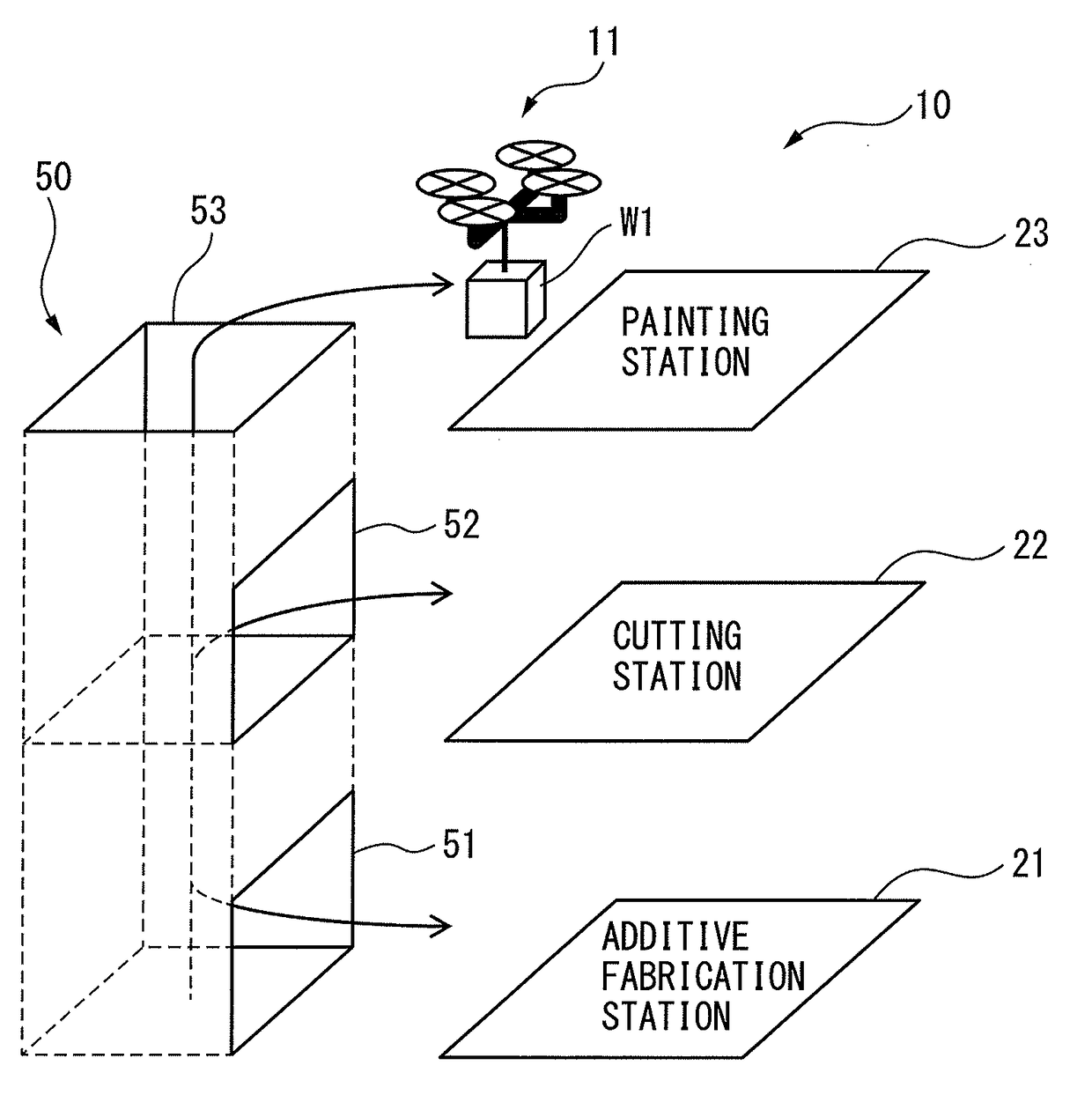
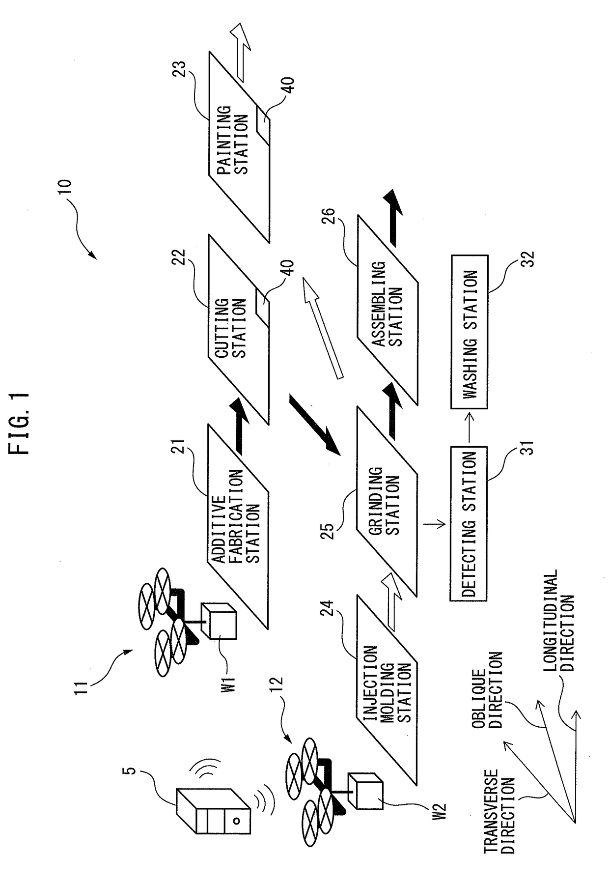
[0025]FIG. 1 is a diagram of a manufacturing system according to the present invention. As shown in FIG. 1, a manufacturing system 10 according to the present invention mainly includes a plurality of manufacturing process stations 21 to 26 and at least one of drones 11 and 12.

[0026]In an example shown in FIG. 1, the manufacturing process stations 21 to 26 include an additive fabrication station 21 for performing additive fabrication using a workpiece, a cutting station 22 for cutting a workpiece, a painting station 23 for painting a workpiece, an injection molding station 24 for molding a workpiece by injection molding, a grinding station 25 for grinding a workpiece, and an assembling station 26 for asse...


PUM

PropertyMeasurementUnit
corrosionaaaaaaaaaa
poweraaaaaaaaaa
time intervalsaaaaaaaaaa

Abstract

A manufacturing system includes a plurality of manufacturing process stations for processing a workpiece, and at least one drone for transferring the workpiece among the manufacturing process stations. It is preferable that the manufacturing system includes a detecting station for detecting contamination or corrosion of the at least one drone, and a washing station for washing the at least one drone.

Description

BACKGROUND OF THE INVENTION[0001]1. Field of the Invention[0002]The present invention relates to a manufacturing system in which a workpiece is transferred among a plurality of manufacturing process stations.[0003]2. Description of the Related Art[0004]In general, a manufacturing system includes a plurality of manufacturing process stations for processing workpieces. For the sake of efficiency, a manufacturing system for manufacturing of a small variety of products in large quantities has been demanded. Thus, in the manufacturing system, the sequence of processing and assembling of products is standardized, and all workpieces are successively transferred along a single transfer route among manufacturing process stations. Specifically, the manufacturing process stations are connected by transfer means, e.g., conveyor belts. Such a manufacturing system can manufacture products at regular time intervals.[0005]For example, Japanese Unexamined Patent Publication (Kokai) No. 03-142150 dis...

Claims


Application Information

Patent Timeline
Patent Type & Authority Applications(United States)
IPC IPC(8): B64C39/02B29C67/00B29C69/00H04L29/08B33Y30/00B33Y40/00G08G5/00B64D47/08B29C45/03B29C31/00
CPCB64C39/024B29C45/03B29C67/0051B29C69/001B29C31/008B64C2201/128B33Y40/00G08G5/003B64D47/08H04L67/125B33Y30/00G05D1/101Y02P90/80B64U2101/60B64U10/13B64U2201/20
Inventor MIURA, MASAHIRO
Owner FANUC LTD
Why Eureka
Try Eureka