Mesh and methods and apparatus for forming and using mesh

a technology of mesh and mesh plate, applied in the direction of magnetic materials, magnetic bodies, protective garments, etc., can solve the problems of limited material that may be used, limited the practical size of link elements, time-consuming and laborious to manufacture chain mail/mesh using traditional methods, etc., and achieves strong structural integrity and attractive appearance

Active Publication Date: 2007-02-22
HAMMOCK IP LTD
View PDF21 Cites 11 Cited by
  • Summary
  • Abstract
  • Description
  • Claims
  • Application Information

AI Technical Summary

Benefits of technology

[0007] It is a further object of the present invention to provide mesh having strong structural integrity and an attractive appearan

Problems solved by technology

It has been time-consuming, labourious and expensive to manufacture chain mail/mesh using traditional methods.
Such methods have a

Method used


Image

  • Mesh and methods and apparatus for forming and using mesh
  • Mesh and methods and apparatus for forming and using mesh
  • Mesh and methods and apparatus for forming and using mesh

Examples


Embodiment Construction

[0049] An embodiment of the present invention includes a method of forming mesh in which the link elements may be in the form of unjoined closed loops. However, the link elements may take many forms including forms having a single aperture therethrough, such as rings, forms having multiple apertures etc.

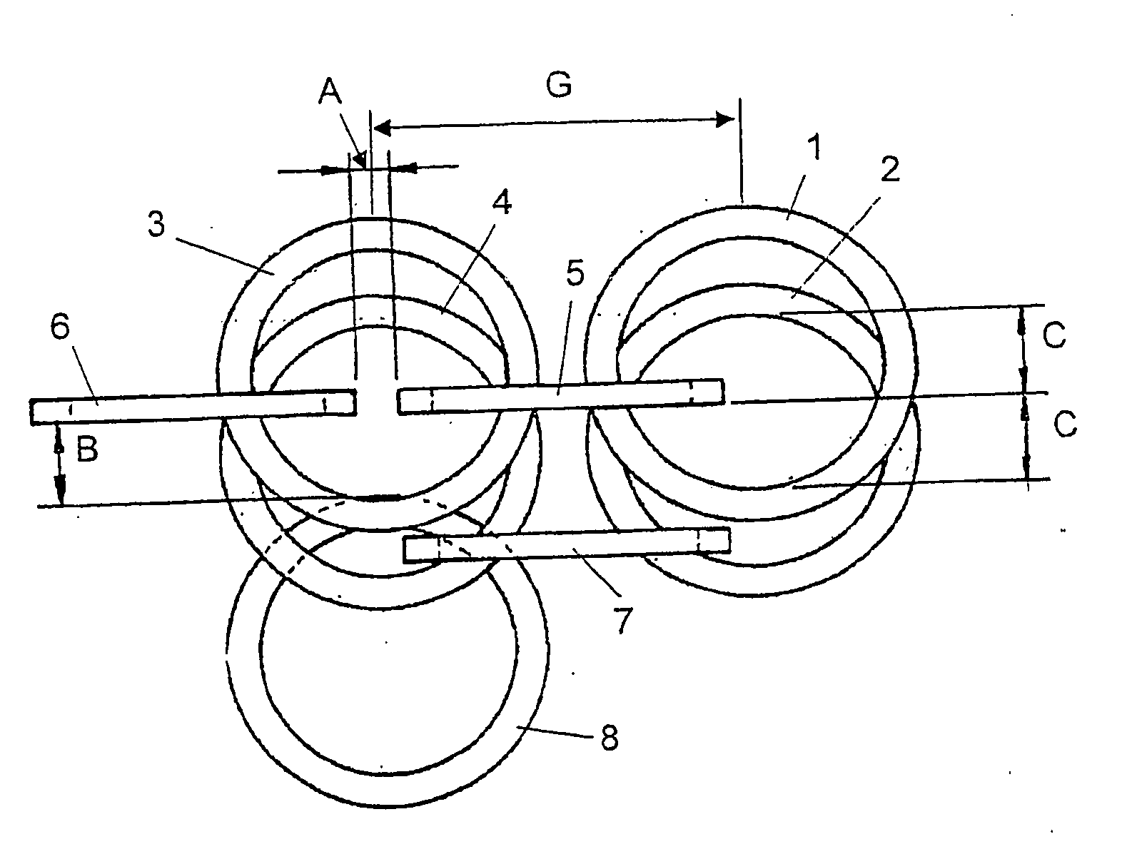
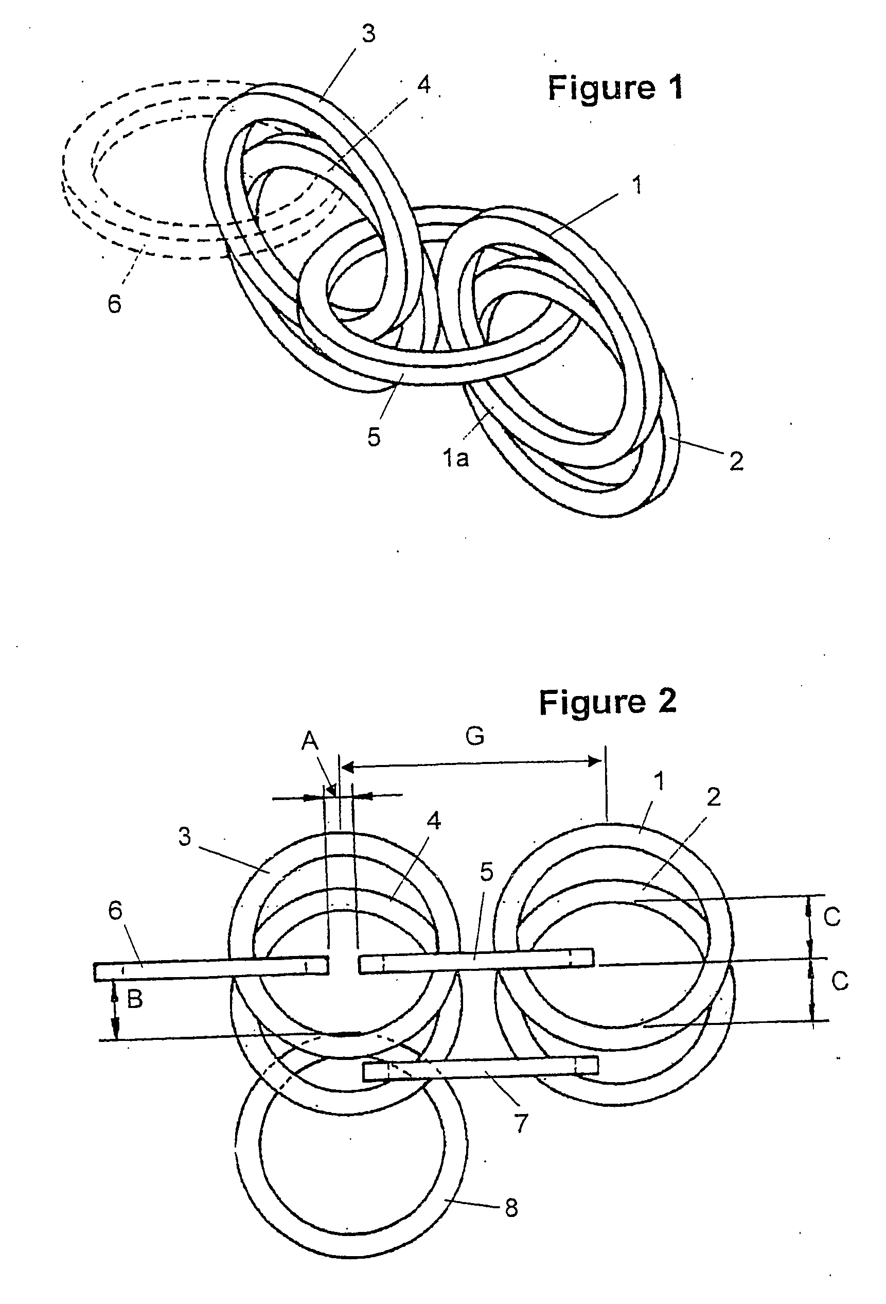
[0050] Referring to FIG. 1 a method for continuously producing mesh is described. Preformed rings 1 to 4 are arranged in a first orientation with pairs 1, 2 and 3, 4 arranged so that portions of their central apertures overlap. Further such pairs may be provided in a row at spaced intervals in the plane of rings 1 to 4 to form a length of mesh as required. A ring 5 may then be moulded so that it passes through the central apertures of rings 1 to 4 as shown. Ring 6 illustrates how further rings may simultaneously be formed along row.

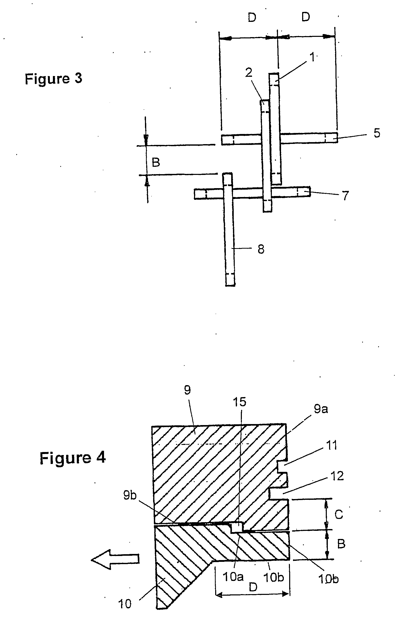
[0051] Referring now to FIGS. 2 and 3 the production of a subsequent row of mesh is described. Ring 3 in FIG. 1 assumes the position of ring 4 in FIG. 2...


PUM

PropertyMeasurementUnit
Flexibilityaaaaaaaaaa
Shapeaaaaaaaaaa
Water absorptionaaaaaaaaaa

Abstract

A method of forming a mesh by a moulding a link element around other link elements to form a mesh in which the interlinking link elements are formed as continuous unjoined loops by a moulding process. An apparatus for forming a mesh including a plurality of first cavities for accommodating first link elements and a plurality of second cavities for forming interlinking link elements. The method and apparatus allow the continuous production of mesh formed of a range of materials including plastics materials.

Description

CROSS REFERENCE TO PRIORITY APPLICATIONS [0001] This application is a Continuation of PCT / NZ2004 / 000104, filed 27 May 2004, and is a Continuation-In-Part of PCT / NZ2004 / 000033, filed 23 Feb. 2004 and claiming the benefit of NZ Application No. 523971, filed 12 Mar. 2003, each incorporated herein by reference in its entirety.FIELD OF THE INVENTION [0002] The present invention relates to methods and apparatus for forming mesh utilising moulded interlinking link elements. The invention also relates to mesh formed by the method of the invention, products incorporating the mesh and methods of using the mesh. Where the term “mesh” is used in this specification it means a mesh formed of interlinking link elements, such as rings. BACKGROUND [0003] Mesh formed of interlinking link elements is best known in the form of chain mail. Chain mail has traditionally been formed by interconnecting closed metal rings with open metal rings and then closing the open rings by a process such as mechanical d...

Claims


Application Information

Patent Timeline
IPC IPC(8): B22D7/00A41D31/00B21F31/00B21L5/00B21L5/02B21L19/00B22D19/00B22D19/04B22D25/00B22D25/02B29C45/00B29C45/14
CPCB21F31/00B22D25/023Y10T442/188Y10T442/195Y10T442/191Y10T442/184Y10T428/2481Y10T428/17Y10T428/12Y10T428/24273B21L5/02B22D19/04B22D25/02
Inventor HORSHAM, KAYNE BRUCE
Owner HAMMOCK IP LTD
Why Eureka
Try Eureka