Systems and methods for tuning an antenna configuration in a mobile communication device

a mobile communication device and antenna configuration technology, applied in the field of mobile communication devices, can solve the problems of poor call quality, dropped calls, poor reception, etc., and achieve the effect of improving reception and improving signal quality

Inactive Publication Date: 2007-02-22
KYOCERA CORP
View PDF32 Cites 122 Cited by
  • Summary
  • Abstract
  • Description
  • Claims
  • Application Information

AI Technical Summary

Benefits of technology

[0014] In one aspect, a primary antenna can be used to receive signals. When it is determined that the primary antenna configuration is experiencing a fade, then a secondary antenna can be coupled to the receiver, e.g., via the signal adjusting network, such that the signals from the secondary receiver can be combined with the signals from the primary receiver in order to improve reception.
[0015] In another aspect, a detector can be included in the mobile communication device and configured to detect when a jammer is present. When the detector detects that a jammer is present, the phase and / or magnitude of the signals being received by one or more of the plurality of antennas can be adjusted so as to improve the signal quality.

Problems solved by technology

Users of mobile communication devices, such as cellular telephones, Personal Digital Assistants (PDAs) or laptop computers that include wireless capability, etc., often experience performance problems, such as dropped calls, poor call quality, and an inability to connect with the network.
Such problems are often the result of interference from other wireless signals in the area.
Additionally, however, such problems can also be the result of what is called multi-path interference.
At times the multi-path signals will combine constructively, but at other times the signals will combine destructively, i.e., the signals will combine in such a manner that they at least partially cancel each other out, or interfere with each other.
Destructive multi-path combining, or interference, can lower the signal-to-noise ratio in the receiver, and effect other signal parameters, causing the problems referred to above.
Such destructive multi-path interference is often referred to as fading, i.e., it causes the signal as seen by the mobile communication device receiver to fade out.
Another source of interference in communication systems is jamming transmissions.
As used herein, however, jamming can include interference that is not intentional, for example transmissions from other mobile communication devices.
Obviously, having two antennas receiving highly correlated signals is not necessarily helpful, since problems with the received signal for open of the antennas will also be experienced by the other antenna.
Thus, an antenna that has a different polarity relative to another antenna can provide uncorrelated signals relative to the other antenna even if the antennas are co-located.
A drawback to such conventional approaches, however, is that only one antenna configuration is used at a given time.

Method used


Image

  • Systems and methods for tuning an antenna configuration in a mobile communication device
  • Systems and methods for tuning an antenna configuration in a mobile communication device
  • Systems and methods for tuning an antenna configuration in a mobile communication device

Examples


Embodiment Construction

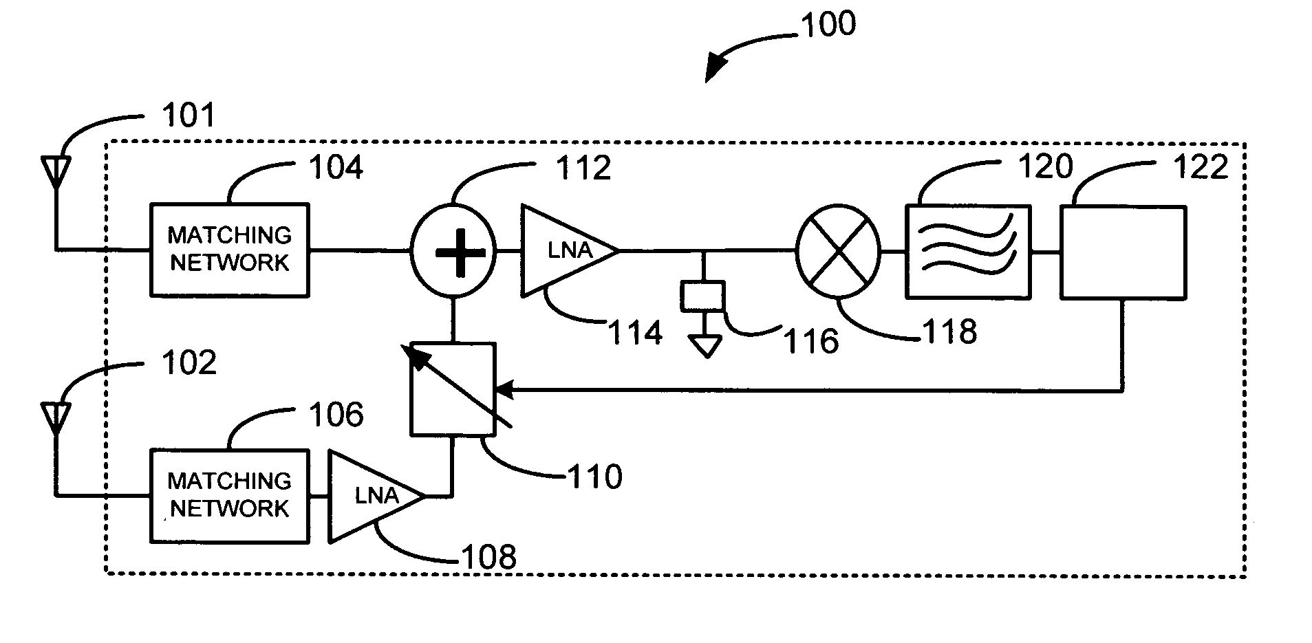
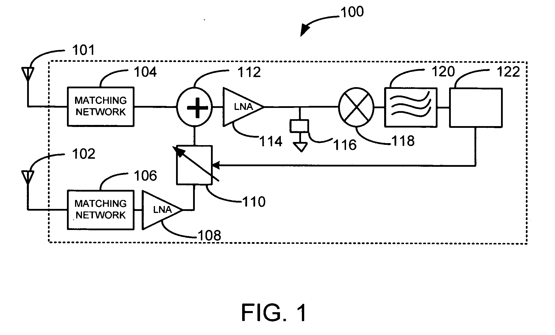
[0023]FIG. 1 is a diagram illustrating various components comprising a mobile communication device 100. The components include a plurality of antennas, two of which are shown by way of example. These two antennas are antennas 101 and 102. As can be seen, antennas 101 and 102 are spatially diverse, i.e., separated by a distance, with respect to each other. In addition, each of antennas 101 and 102 can have a unique polarity in relation to the other, and / or a unique radiation pattern relative to one another. The combination of position, radiation, pattern, polarity, etc., of antennas 101 and 102 can be referred to as an antenna configuration. Thus, mobile communication device 100 can be said to comprise two antenna configurations. The purpose, as explained below, of including multiple antenna configurations is to enable device 100 to receive signals from multiple antennas that will be uncorrelated with respect to each other, so that the various signals can be used to improve receiver ...


PUM


Abstract

A mobile communication device comprises a plurality of spatially and / or polar diverse antenna configurations. Signals received by each of the plurality of antenna configurations are combined in a combiner and passed to a rake receiver that can be configured to combine the signals received by each of the plurality of antenna configurations for further processing. The mobile communication device can comprises a signal adjusting network that can be configured to adjust the phase and / or magnitude of signals being received by one of the antennas.

Description

FIELD OF THE INVENTION [0001] The present invention relates generally to mobile communication devices, and more particularly to selecting antenna configurations in a mobile communication device. BACKGROUND OF THE INVENTION [0002] Users of mobile communication devices, such as cellular telephones, Personal Digital Assistants (PDAs) or laptop computers that include wireless capability, etc., often experience performance problems, such as dropped calls, poor call quality, and an inability to connect with the network. Such problems are often the result of interference from other wireless signals in the area. Additionally, however, such problems can also be the result of what is called multi-path interference. [0003] The term multi-path is a term that describes how a signal transmitted in a wireless environment travels along multiple paths from the transmission source to the destination or receiver. For example, when a base station transmits a signal to a mobile communication device, the...

Claims


Application Information

Patent Timeline
Patent Type & Authority Applications(United States)
IPC IPC(8): H04B1/02
CPCH04B1/1027H04B1/7115H04B7/0845
Inventor POILASNE, GREGORYCAMARILLO, RICHARD J.
Owner KYOCERA CORP
Why Eureka
Try Eureka